Pump Protection Method and System

Active Publication Date: 2018-11-01
FMC KONGSBERG SUS
View PDF0 Cites 3 Cited by
  • Summary
  • Abstract
  • Description
  • Claims
  • Application Information

AI Technical Summary

Benefits of technology

[0029]It may be advantageous that the step of calculating the torque of the pump comprises compensating for mechanical and/or electrical losses in the system, e.g. losses at a pump shaft of the p

Problems solved by technology

However, such multiphase flow meters are expensive and a sig

Method used


Image

  • Pump Protection Method and System
  • Pump Protection Method and System
  • Pump Protection Method and System

Examples


Embodiment Construction

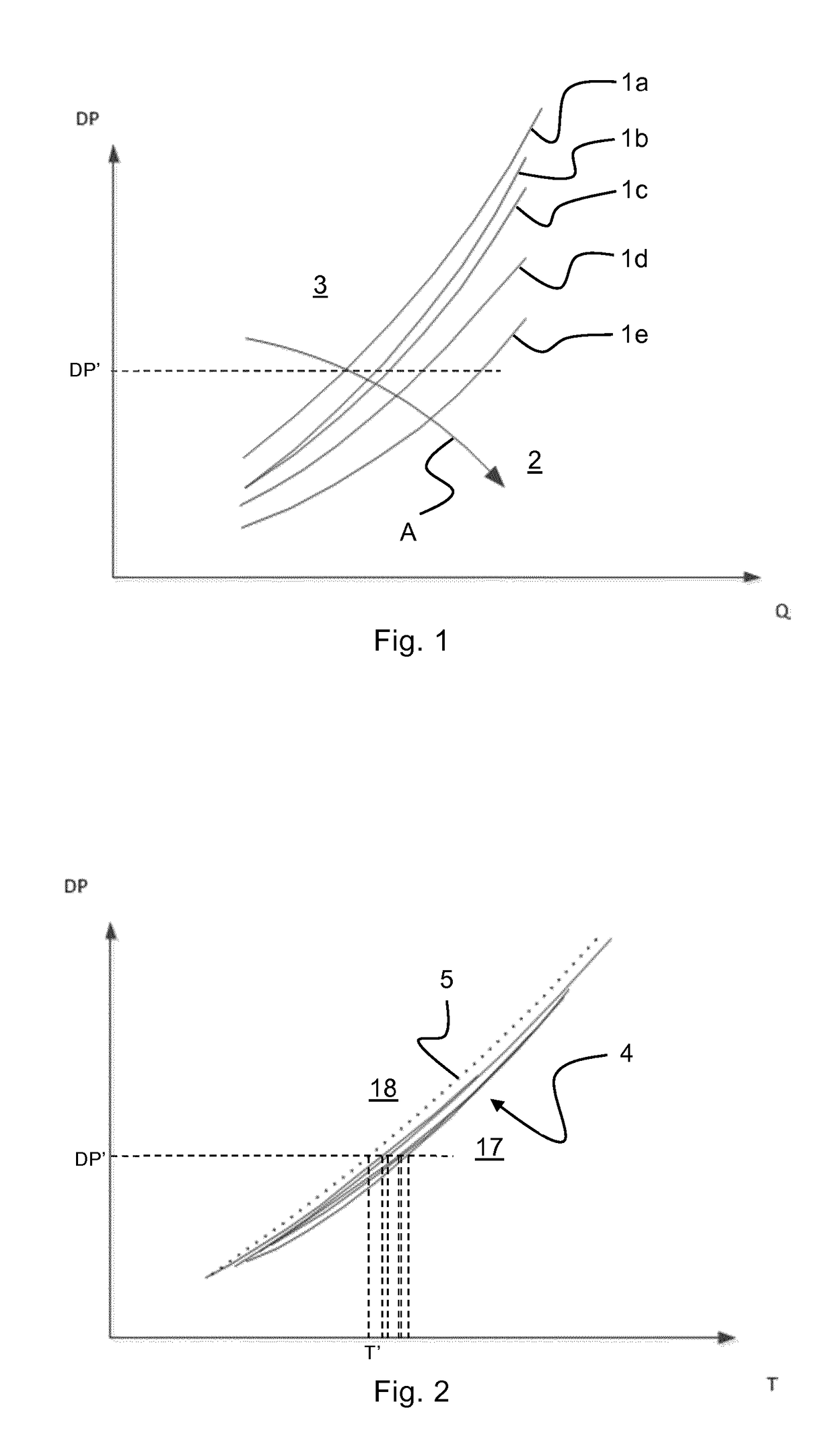
[0038]FIG. 1 discloses a conventional pump limit characteristics diagram 1 for a hydrocarbon pump where the differential pressure DP across the pump is mapped as a function of the volumetric flow Q through the pump for different gas volume fractions of the fluid being pumped. This type of diagram is conventionally referred to as a DP-Q diagram. The diagram discloses a plurality of pump limit characteristics curves 1a-1e for different gas volume fraction values. The curve la represents the maximum flow limit for a first gas volume fraction, GVFa, the curve 1b represents the maximum flow limit for a second gas volume fraction, GVFb, etc., where GVFabcde, and where the curves 1a-1e define an impermissible operating region 2 and a permissible operating region 3 of the pump. As is indicated by the arrow A, for a given differential pressure value DP′ the pump limit characteristics curves 1a-1e shift towards higher flow values when the gas volume fraction increases. Consequently, in order ...


PUM


Abstract

A method of protecting a hydrocarbon pump (6) from excessive flow rates in a system for pumping a hydrocarbon fluid, which system comprises said pump and an electrical motor (10) for driving the pump. The method comprises the steps of: for each of a plurality of gas volume fraction values of the hydrocarbon fluid, establishing a maximum torque limit for the pump by mapping the maximum allowable torque of the pump as a function of the differential pressure across the pump, thereby creating a plurality of maximum torque curves (4), each representing the maximum torque limit for a unique gas volume fraction value; from the plurality of maximum torque curves (4), establishing a master maximum torque curve (5) which represents the maximum torque limit for all gas volume fraction values; monitoring the torque of the pump and the differential pressure across the pump; based on the monitored differential pressure (DP′) and using the master maximum torque curve, establishing a maximum allowable torque (T′) for the pump; and taking a predetermined action if the monitored torque exceeds the established maximum allowable torque (T′), e.g. raising an alarm and/or shutting down the system.

Description

FIELD OF THE INVENTION[0001]The present invention relates to a method of protecting a hydrocarbon pump from excessive flow rates in a system for pumping a hydrocarbon fluid, which system comprises said pump and an electrical motor for driving the pump.[0002]The present invention also relates to a system comprising a pump and an electrical motor for driving the pump, which system operates according to the method.[0003]In particular, the present invention relates to a method and a system for pumping a fluid comprising hydrocarbons in a subsea hydrocarbon production or processing complex.BACKGROUND[0004]Basically, multiphase pumps are used to transport the untreated flow stream produced from oil wells to downstream processes or gathering facilities. This means that the pump may handle a flow stream (well stream) from 100 percent gas to 100 percent liquid and every imaginable combination in between. In addition to hydrocarbons, the flow stream can comprise other fluids, e.g. water, and ...

Claims


Application Information

Patent Timeline
IPC IPC(8): F04B49/06
CPCF04B49/065F04B49/06F04B17/03F04B47/00F04B47/06F04B49/00F04B49/10F04B49/103F04D13/06F04C2270/015F04D15/0088F04B2203/0207F04C14/28F04C28/28F04D15/0077F04B51/00F04C2210/40F04B15/00F04D27/001F04B2205/09F04B49/106
Inventor TODAL, KARENGROTTERUD, HELGE
Owner FMC KONGSBERG SUS
Why Eureka
Try Eureka