Cooking device with multiple heating units

a technology of cooking device and heating unit, which is applied in the field of household electric appliances, can solve the problems of high practicability of every function, complex structure, and inability to meet the needs of the user, and achieve the effect of preventing oil fum

Active Publication Date: 2018-11-08
SHENZHEN ZEZHI INTPROP CO LTD
View PDF23 Cites 71 Cited by
  • Summary
  • Abstract
  • Description
  • Claims
  • Application Information

AI Technical Summary

Benefits of technology

[0007]Concerning the above situations, it is necessary to provide a cooking device with a compact structure that can prevent oil fume.

Problems solved by technology

Since the single pot has multiple functions, the practical quality of every function is not high, i.e., comprehensive but not specialized.
However, the structures of the multiple-functional pots in the related art described above, which are similar to that of the conventional stove, are still relatively complicated but not compact.
In addition, as to the fog in the rice cooker, a vacuum insulation device is disclosed by Li Wen Qing in patent (Chinese patent application publication number No. 200510037553.5), which can vacuumize the inner pot thereof and thus delay in getting the preserved rice yellow and sour.
However, such a design of electric cooker doesn't help in oil fumes generated during cooking.
However, in the cooking device disclosed in patent (Chinese patent application publication number No. 200910204171.5), the inlet nozzles connected with outside are arranged at the bottom of the cooking device, the air in the cooking device will enter the inner pot after being heated, and in this way, it is not easy to replace the steam or the oil fume inside with the air outside, it is likely that more steam or oil fume leaks out when opening the lid, thereby causing air pollution.

Method used


Image

  • Cooking device with multiple heating units
  • Cooking device with multiple heating units
  • Cooking device with multiple heating units

Examples


Embodiment Construction

[0018]The cooking device of the present invention is further described in detail with reference to the accompanying drawings and embodiments.

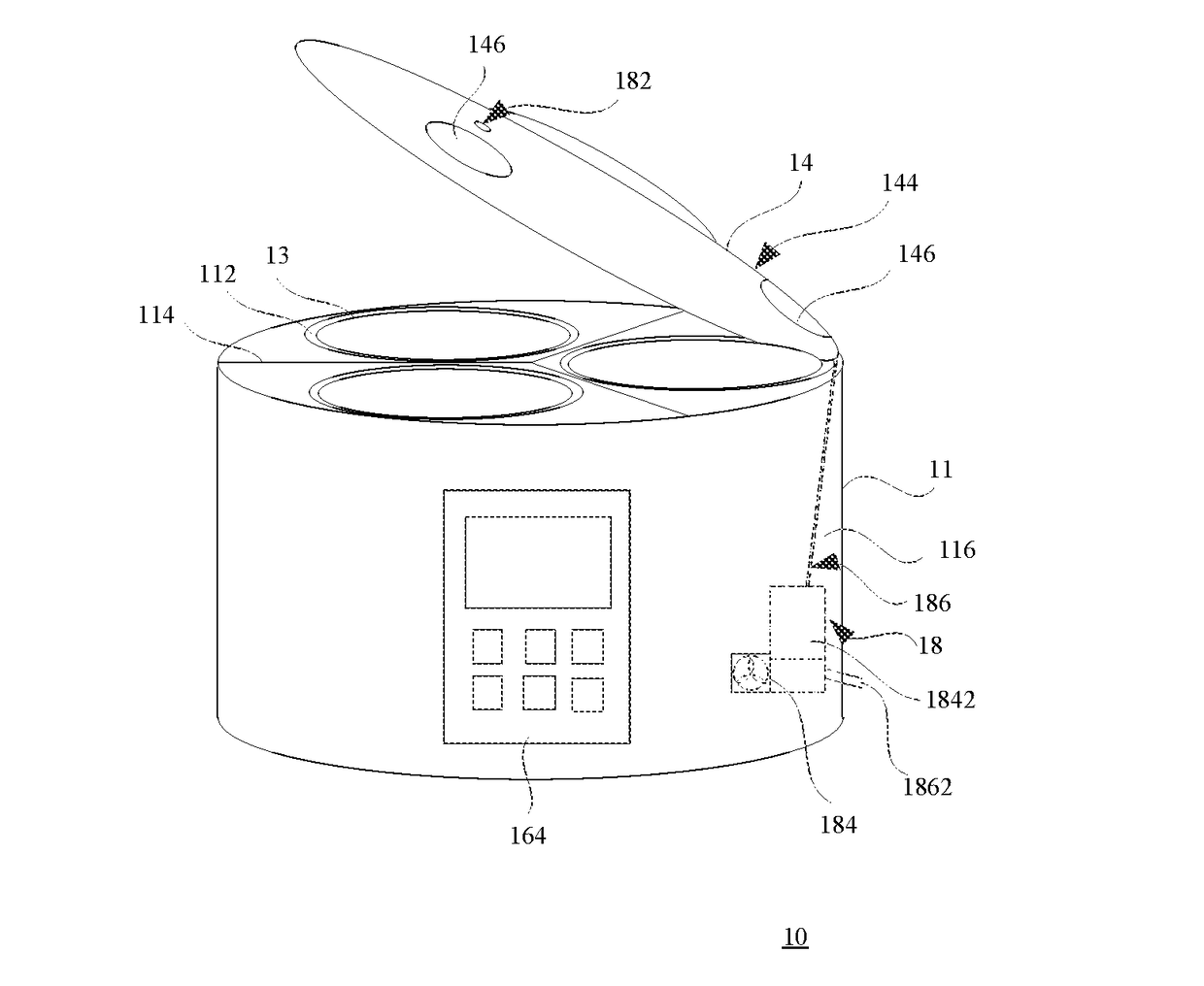
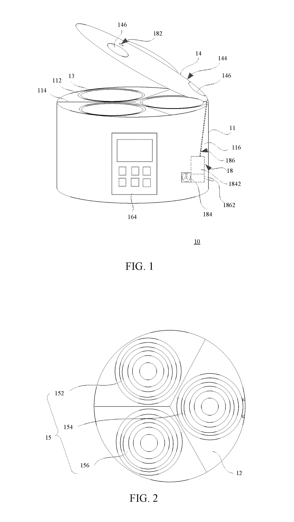
[0019]Referring to FIG. 1 through FIG. 4, a cooking device 10 of a first exemplary embodiment of the present invention includes a housing 11, a base 12, inner pots 13, a lid 14, a heating module 15, a control module 16 and an exhaust module 18. The housing 11 is arranged on the base 12. The housing 11 has a storage compartment 112. The inner pots 13 are put in the storage compartment 112. The control module 16 includes a processor 162 and an input panel 164 connected with the processor 162. The heating module 15 is arranged inside the storage compartment 112, and includes multiple bottom heating units 152, 154 and 156, which are independent from each other. The bottom heating units 152, 154 and 156 are respectively connected with the processor 162. There are a plurality of inner pots 13 arranged inside the storage compartment 112 and correspond...


PUM


Abstract

A cooking device includes a base, a housing, partition walls, a lid, a control module, an exhaust module, a connecting electrode and a heating module. The exhaust module includes an air-filled element, an air-extraction element, an inlet passage and an exhaust passage. The air-extraction element is used to exhaust fog or oil fume generated in the plurality of inner pots. The connecting electrode is arranged in a middle position of the base. The heating module includes: bottom heating units disposed different locations inside a storage compartment of the housing respectively and connected with the processor individually; second heating units arranged on the partition walls and connected with the connecting electrode by wires inside the partition walls; and third heating units arranged on the inner wall of the housing.

Description

CROSS-REFERENCE TO RELATED APPLICATIONS[0001]This application is a continuation-in-part of U.S. patent application Ser. No. 15 / 697,514, filed on Sep. 7, 2017, which is a continuation application of U.S. patent application Ser. No. 15 / 054,945, filed on Feb. 26, 2016, now U.S. Pat. No. 9,795,250, the disclosures of which are incorporated herein by references in their entirety.TECHNICAL FIELD[0002]The present invention relates to a household electric appliance, and particularly to a cooking device with a compact structure that can prevent oil fumes.DESCRIPTION OF RELATED ART[0003]Cooking food is one of the essential activities in people's lives. With the development of technology, the type and style of each of the cooking methods and the cooking devices has become increasingly diverse. However, each of the cooking devices unveiled on the market generally is one single pot, and the single pot has integrated functions of sautéing food, steaming food, barbecuing food, etc. Since the singl...

Claims


Application Information

Patent Timeline
Patent Type & Authority Applications(United States)
IPC IPC(8): A47J27/092A47J36/38A47J37/12A23L5/10A47J36/32A47J27/00A47J27/04
CPCA47J2027/043A23L5/17A47J27/092A47J36/38A47J36/32A47J27/004A47J37/128A47J36/321A47J27/122A47J37/108A47J27/086A47J37/105A47J36/16
Inventor HUANG, ZHONGHUI
Owner SHENZHEN ZEZHI INTPROP CO LTD
Why Eureka
Try Eureka