Method for determining a patient specific locally varying margin

Active Publication Date: 2018-11-08
KONINKLJIJKE PHILIPS NV
View PDF4 Cites 5 Cited by
  • Summary
  • Abstract
  • Description
  • Claims
  • Application Information

AI Technical Summary

Benefits of technology

[0022]According to further embodiments of the invention, the second medical image is an image suitable to be used for segmentation of the treatment target. This could for example be a T2w image. This embodiment is advantageous, because in this way an image that needs to be acquired anyway in order to delineate the treatment target can be used in addition to determine the patient specific locally varying margin. This embodiment is even more advantageous when the second medical image is an MRI image and when the first medical image is an MRI image suitable to be used for a generation of a pseudo CT image of the treatment target. This is even more advantageous, because in this way the images that need to be acquired anyway to support an MRI based radiotherapy planning can be used in addition to determine the patient specific locally varying margin. In this way, the information on which the patient specific locally varying margin is based can be almost or completely obtained for free in the sense that no extra time is needed for the image acquisition.
[0023]According to further embodiments of the invention, the method further comprises a step of displaying the displacement of the first location and the displacement of the second location betw

Problems solved by technology

The challenge in the whole process is to distribute a high dose to the cancer ce

Method used


Image

  • Method for determining a patient specific locally varying margin
  • Method for determining a patient specific locally varying margin
  • Method for determining a patient specific locally varying margin

Examples


Embodiment Construction

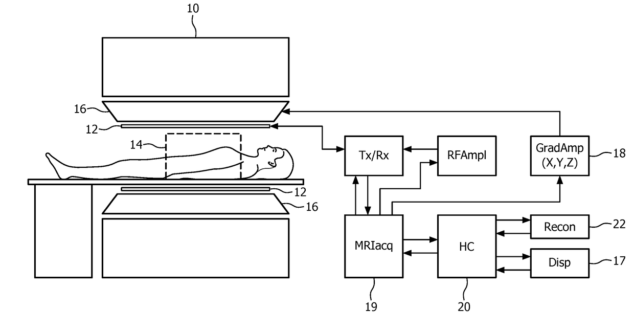
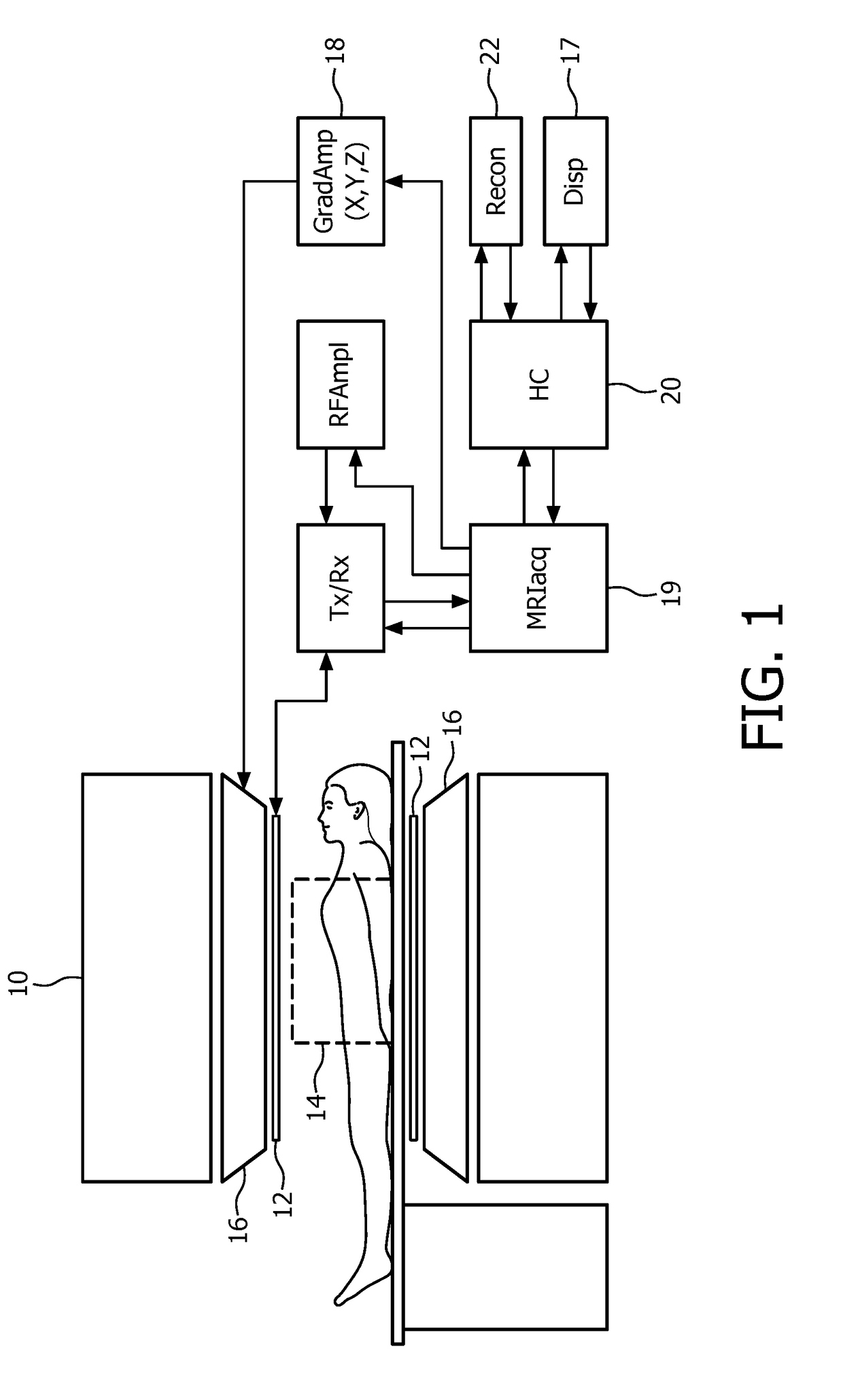
[0034]FIG. 1 illustrates diagrammatically a medical imaging system, in this case a magnetic resonance imaging (MRI) system in which the invention is used. The MRI system comprises a main magnet 10 which generates a steady homogeneous main magnetic field within the examination zone 14. This main magnetic field causes a partial orientation of the spins in the object to be examined along the field lines of the main magnetic field. An RF system is provided with one or more RF antennae 12 to emit an RF excitation electromagnetic field into the examination zone 14 to excite spins in the body of the object to be examined. The relaxing spins emit magnetic resonance signals in the RF range which are picked up by the RF antennae 12, notably in the form of RF receiving coils. Further, gradient coils 16 are provided to generate temporary magnetic gradient fields, notably read gradient pulses and phase encoding gradients. These gradient fields usually are orientated in mutual orthogonal directio...


PUM


Abstract

It is an object of the invention to provide for an improved radiation treatment. According to a first aspect of the invention, this object is achieved by a method for determining a patient specific locally varying margin on a treatment target and/or an organ at risk in order to compensate for local intrafraction motion expected during a radiotherapy fraction to be delivered over a radiotherapy fraction time interval. The patient specific locally varying margin is determined based on a displacement and/or an estimate of the displacement of at least a first location and a second location on the treatment target and/or organ at risk. The method comprises steps of: acquiring a first medical image of the treatment target and/or the organ at risk and acquiring a second medical image of the treatment target and/or the organ at risk, wherein the time between the acquisition of the first medical image and the second medical image is similar to the radiotherapy fraction time interval and determining of positions of the first location and the second location in the first medical image and in the second medical image and using the determined positions for determining the patient specific locally varying margin around the treatment target and/or organ at risk.

Description

FIELD OF THE INVENTION[0001]The invention relates to the field of radiation therapy.BACKGROUND OF THE INVENTION[0002]Radiation therapy planning is a complex process, comprising four steps:[0003]1. On a given patient image a treatment target and one or more organs at risk are delineated (manually or by (semi-)automatic methods).[0004]2. Several margins for irradiation inaccuracy, patient motion, or sub-clinical cancer cells outside the visible tumor are added.[0005]3. Then the treatment target and one or more organs at risk are equipped with a number of objectives for the radiation, e.g. maximal / minimal doses.[0006]4. Then a computer program optimizes beam parameters to get as close as possible to those objectives.[0007]The challenge in the whole process is to distribute a high dose to the cancer cells and a low dose to the healthy cells, especially to sensitive organs at risk. For this, a number of unknown parameters have to be estimated, e.g., the tumor spread, the patient motion a...

Claims


Application Information

Patent Timeline
IPC IPC(8): A61N5/10
CPCA61N5/1037A61N5/1039A61N5/1038
Inventor SCHADEWALDT, NICOLEPETERS, JOCHEN
Owner KONINKLJIJKE PHILIPS NV
Why Eureka
Try Eureka