
Tinnitus testing device using brain waves and tinnitus testing method using same

a testing device and brain wave technology, applied in the field of tinnitus testing apparatus using brain waves and testing methods, can solve the problems of no reports of inventions applying the above-described principles to the testing of humans, the patient may have difficulty in daily life, so as to achieve the objective evaluation of tinnitus, effective cooperation in testing, and effective measurement of tinnitus

Active Publication Date: 2013-12-19
IND ACADEMIC CORP FOUND YONSEI UNIV
View PDF2 Cites 9 Cited by
  • Summary
  • Abstract
  • Description
  • Claims
  • Application Information

AI Technical Summary

Benefits of technology

The invention is a method and apparatus for objectively evaluating tinnitus using brain waves generated in response to an auditory stimulus. This approach overcomes the limitations of previous methods that relied on behavioral response. The invention can be used to distinguish tinnitus patients from tinnitus-free people and to measure the effectiveness of tinnitus treatment. The testing method is also more accurate for individuals with different degrees of hearing loss, tinnitus frequency, and loudness. The invention minimizes errors in test results by conducting a second re-verification of initial results. Overall, this invention provides a more reliable and accurate tool for evaluating tinnitus.

Problems solved by technology

Patients who complain of tinnitus may have difficulty with daily life if suffering severely from different sounds in their ears or head.
In current society, despite the gradual upward trend in tinnitus patients as the frequency of exposure to noise has increased, tinnitus is still thought of as an incurable disease that is difficult to treat.
However, to date, there have been no reports of inventions applying the above-described principles to the testing of humans.
However, because it is a subjective testing method that depends on the cooperation of the examinee exposed to an auditory stimulus, there are considerable problems in the testing of elderly and infants who have insufficient understanding of the test procedure.
In addition, it is not easy to ensure objectively with respect to the determination of tinnitus when it is linked to problems of financial compensation of an examinee in whom tinnitus has occurred due to an accident or noise exposure.

Method used


Image

  • Tinnitus testing device using brain waves and tinnitus testing method using same
  • Tinnitus testing device using brain waves and tinnitus testing method using same
  • Tinnitus testing device using brain waves and tinnitus testing method using same

Examples


embodiments

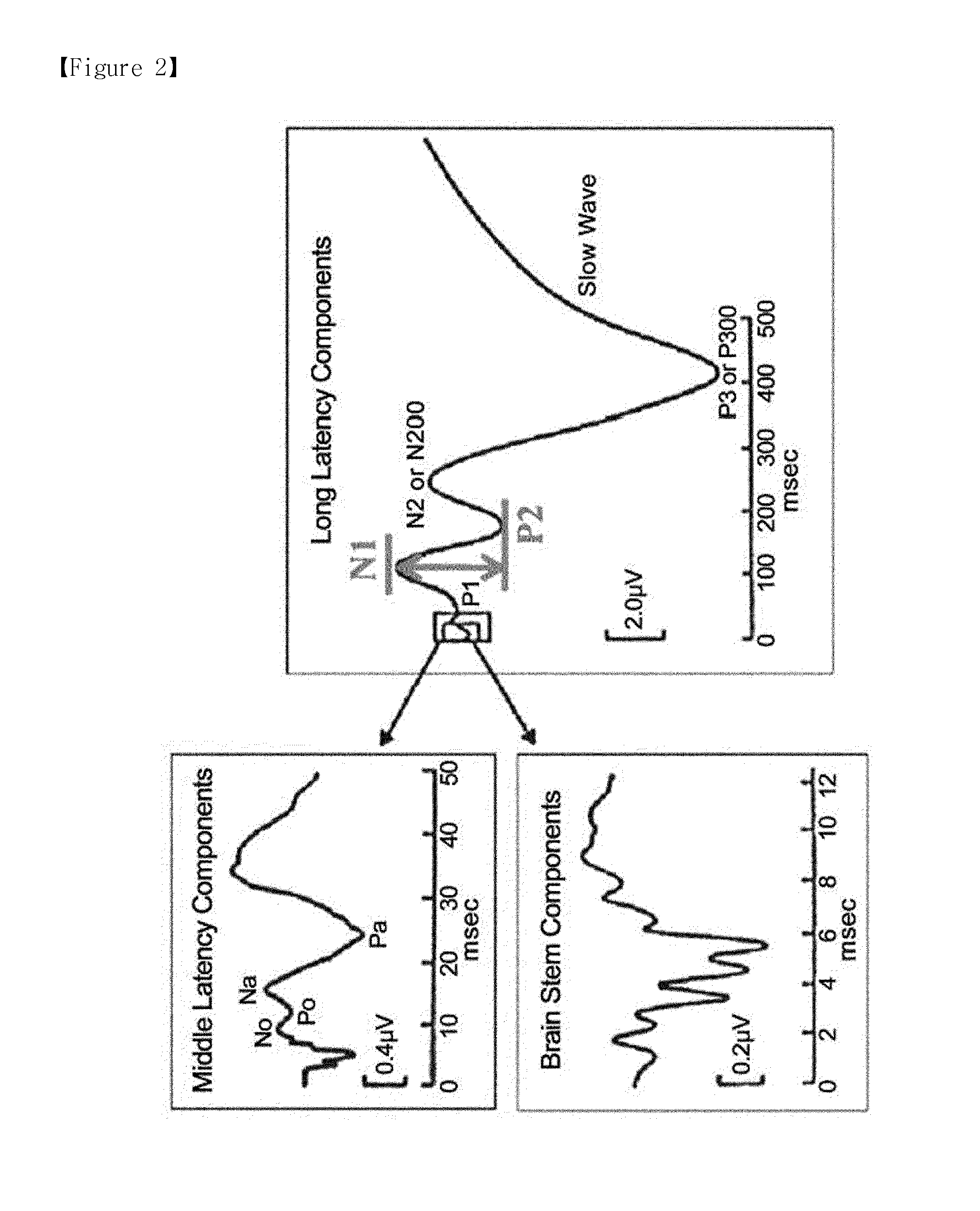
[0053]FIG. 2 is a graph showing in detail the N1 evoke d response and P2 evoked response measured by the tinnitus testing apparatus according to one embodiment of this invention.

[0054]When an auditory stimulus such as sound is applied to the human body, brainwave reactions occur including the Auditory Brain-stem Response (ABR), Middle Latency Response (MLR) and Late Latency Response (LLP).

[0055]Here the Middle Latency Response denotes a reaction occurring between approximately 15 and 50 msec after an auditory stimulus, and Late Latency Response denotes a reaction occurring from approximately 75 to 200 msec, and more specifically from about 80 to 100 msec, after the auditory stimulus; these reactions occur in the central auditory pathway.

[0056]The N1 and P2 reactions correspond to the Late Latency Response; as described below in this specification, by measuring the N1 and P2 reactions and the N1-P2 amplitude, the presence or absence of tinnitus can be measured more objectively.

[0057]...


PUM


Abstract

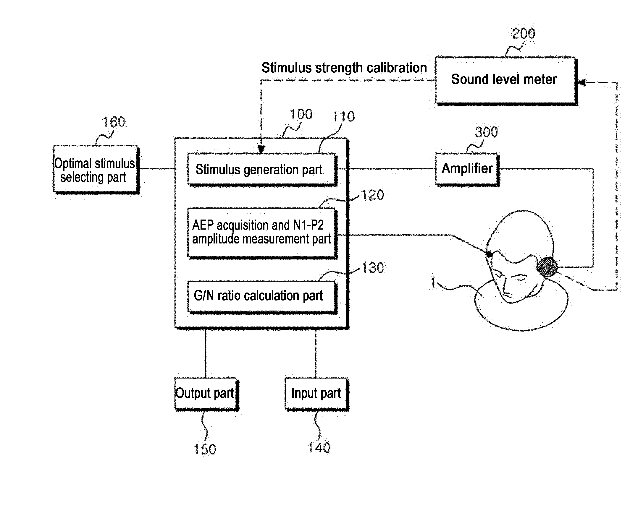
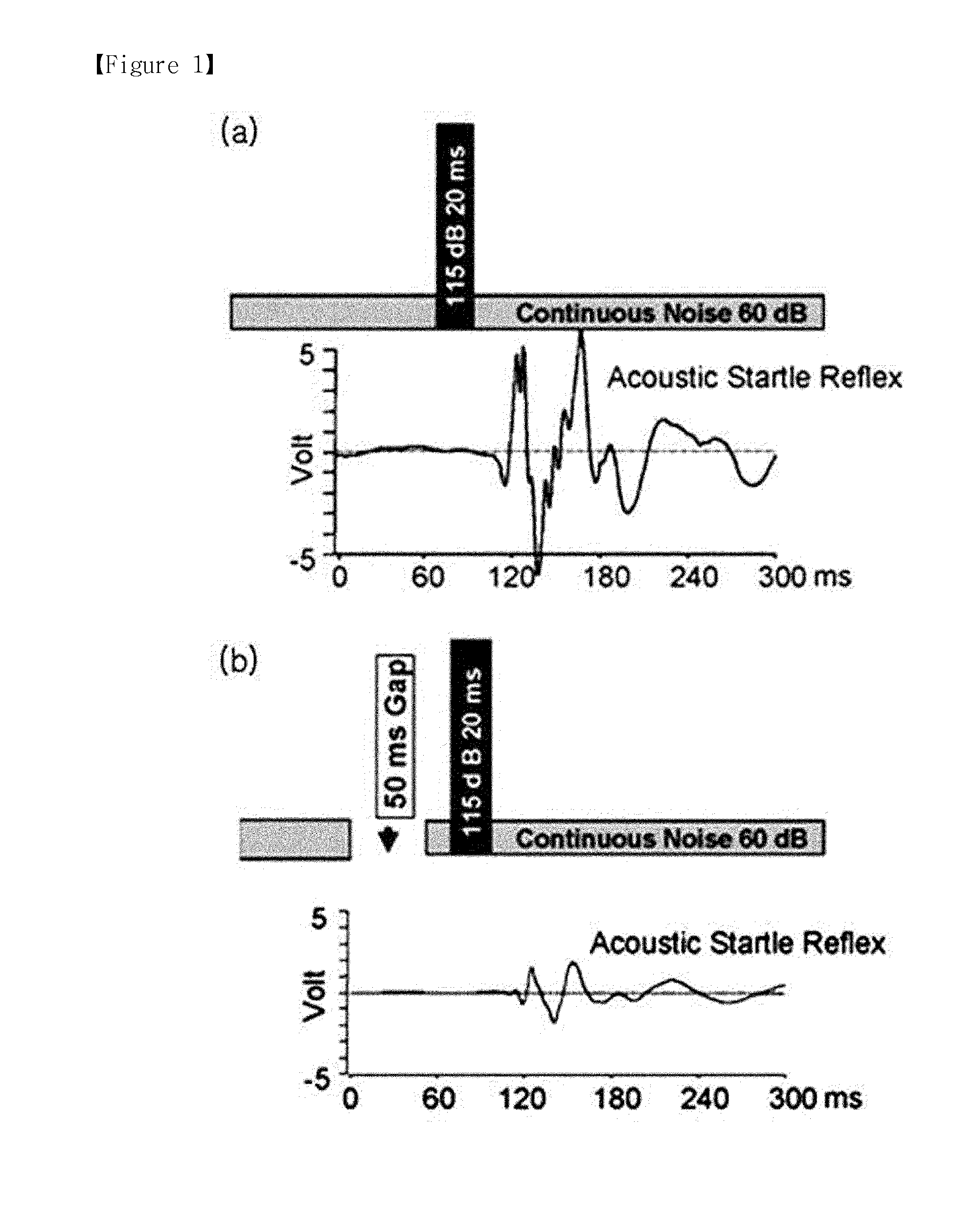
The tinnitus testing apparatus of this invention comprises a control part that in turn comprises: an auditory stimulus generation part that can generate a stimulus; and an AEP acquisition and amplitude measurement part that can acquire auditory evoked potential (AEP) brain waves of a examinee due to said stimulus and measure the specific amplitude of said acquired brainwaves; wherein said auditory stimulus is one or more of: a 1st stimulus containing continuous noise and pulse noise; and a 2nd stimulus containing pulse noise and continuous noise with a silent gap.

Description

TECHNICAL FIELD[0001]This invention relates to a tinnitus testing apparatus using brain waves and testing method for verification of tinnitus using same; more specifically, it relates to a testing apparatus that, compared to subjective methods based on examinee cooperation, can more objectively prove whether tinnitus is present by measuring the brain waves of the examinee, and to a method of testing for tinnitus using this apparatus.BACKGROUND ART[0002]“Tinnitus” refers to the subjective sensation of hearing noise in one's ears. Specifically, it is the state of feeling that one is hearing a sound in the absence of any external auditory stimulus. In a quiet fully soundproofed room, 95% of ordinary persons experience tinnitus of 20 dB (decibels) or less, but this is not referred to clinically as tinnitus; “tinnitus” refers to cases in which noise or sound is heard at a level sufficient to perturb the examinee.[0003]Specifically, tinnitus of this kind can be classified as two types: th...

Claims


Application Information

Patent Timeline
IPC IPC(8): A61B5/12A61B5/04A61B5/048A61B5/0484A61B5/374
CPCA61B5/128A61B5/04845A61B5/04012A61B5/048A61B5/316A61B5/374A61B5/38A61B5/7225A61B5/7235
Inventor SUH, MYUNG WHANPARK, IL YONGOH, SEUNG HARHEE, CHUNG KU
Owner IND ACADEMIC CORP FOUND YONSEI UNIV
Learn More