Supercharge Your Innovation With Domain-Expert AI Agents!

Robot

a robot and robot technology, applied in the field of robots, can solve the problems of troublesome transportation and packing of robots having a configuration of related art, and the difficulty of transporting and packing the entire robot, and achieve the effect of improving workability at the time of transporting and packing the robo

Active Publication Date: 2018-11-08
SEIKO EPSON CORP
View PDF0 Cites 10 Cited by
  • Summary
  • Abstract
  • Description
  • Claims
  • Application Information

AI Technical Summary

Benefits of technology

The robot described in this patent has an arm and connection part on the same side of the base, which makes it easier to transport and pack the robot. This improves workability.

Problems solved by technology

In this case, in the robot described in JP-A-7-124886, the connector and the robot arm are provided on the opposite side via the base, and thereby, it is difficult to transport and pack the entire robot, while both the robot arm and the power supply cable are supported.
Accordingly, it is very troublesome to transport and pack a robot having a configuration of related art.

Method used


Image

  • Robot
  • Robot
  • Robot

Examples


first embodiment

[0054]First, a robot according to a first embodiment will be described.

Basic Configuration of Robot

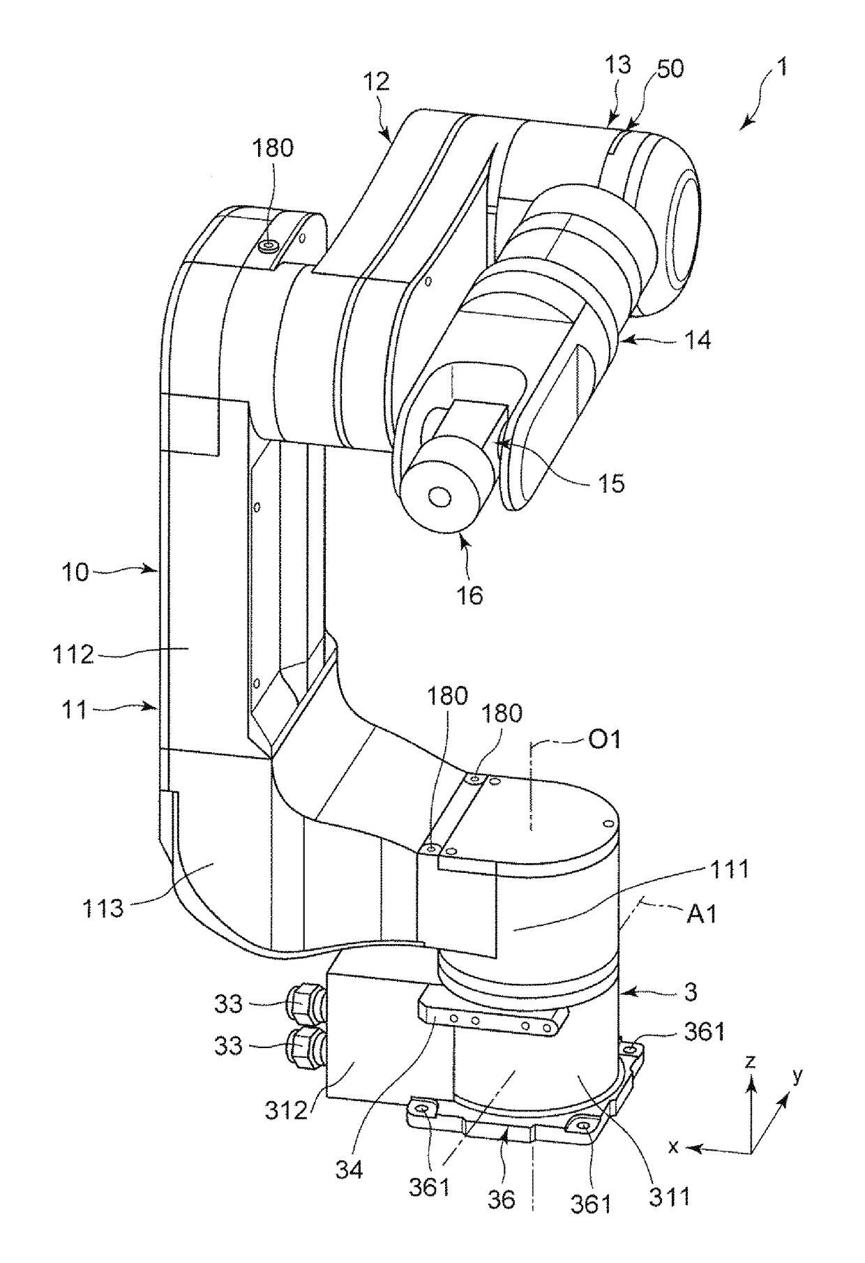
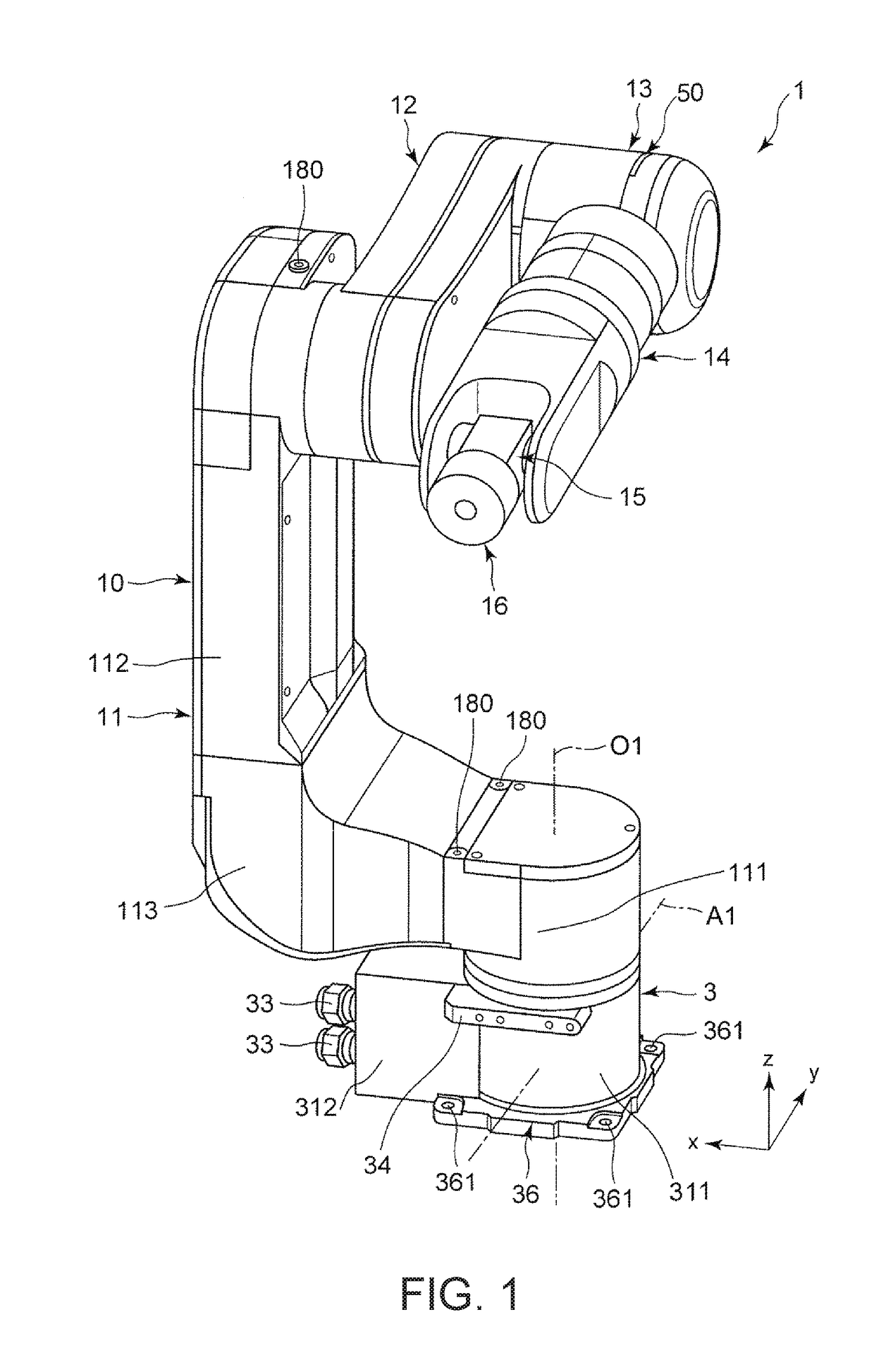
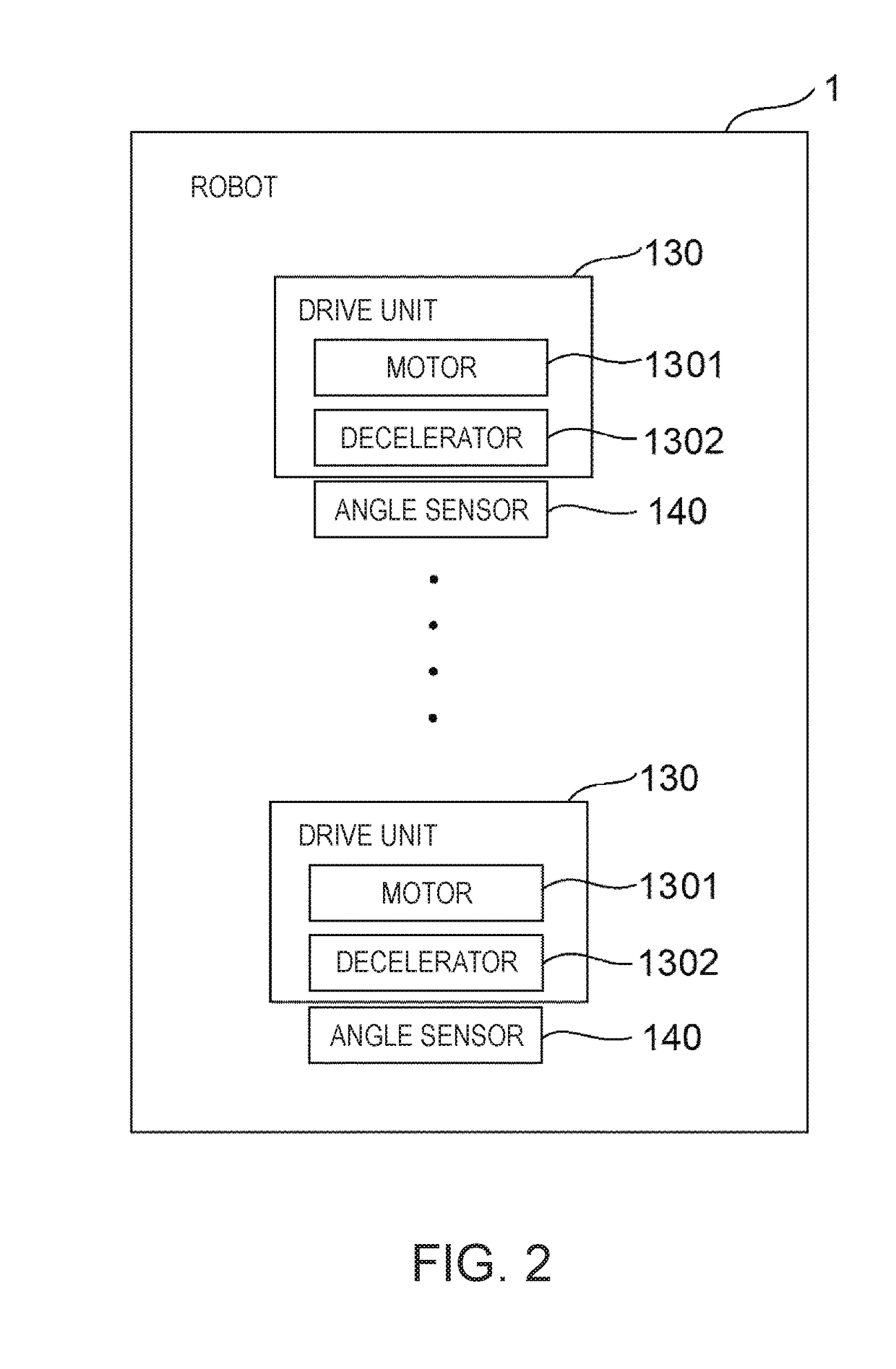
[0055]FIG. 1 is a perspective view of the robot according to the first embodiment. FIG. 2 is a system configuration diagram of the robot illustrated in FIG. 1. FIG. 3 is a schematic front view of the robot illustrated in FIG. 1. FIG. 4 is a schematic side view of the robot illustrated in FIG. 1. Hereinafter, for the sake of convenient description, in each of FIGS. 1, 3, and 4, an x-axis, a y-axis, and a z-axis are illustrated as three axes orthogonal to each other, and a front end side of an arrow indicating each axis is referred to as “+” and a base end side is referred to as “−”. In addition, a direction parallel to the x-axis is referred to as an “x-axis direction”, a direction parallel to the y-axis is referred to as a “y-axis direction”, and a direction parallel to the z-axis is referred to as a “z-axis direction”. In addition, a base 3 side of a robot 1 illustrated in FIG. 1 is r...

second embodiment

[0155]Next, a second embodiment according to the invention will be described.

[0156]FIG. 22 is a side view illustrating a basic posture of a robot arm included in a robot according to a second embodiment. FIG. 23 is a schematic top view illustrating the basic posture of the robot arm included in the robot illustrated in FIG. 22.

[0157]The present embodiment is the same as the above-described embodiment except that a configuration of the robot arm is different. In the following description, the second embodiment will be described by focusing on a difference from the above-described embodiment, and description on the same matter will be omitted.

[0158]A robot 2 illustrated in FIGS. 22 and 23 includes a base 4 and a robot arm 20.

[0159]The base 4 has the same configuration as in the base 3 according to the first embodiment, and includes a housing 411, a plurality of grip portion attaching portions 44, a plurality of connectors 43, and a base attachment member 46 including a plurality of ba...


PUM


Abstract

A robot includes a base; a robot arm that includes an arm which is rotatable around a rotation axis with respect to the base; and a connector that is provided in the base and is capable of being connected to an external wire. The connector is located on a side of the center of gravity more than a line that is perpendicular to a location of a center of gravity of the robot arm when the robot arm is in a basic posture and a line segment passing through the rotation axis and passes through the rotation axis, as viewed from an axial direction of the rotation axis.

Description

BACKGROUND1. Technical Field[0001]The present invention relates to a robot.2. Related Art[0002]In the related art, an industrial robot including a robot arm and an end effector attached to a front end of the robot arm is known.[0003]For example, JP-A-7-124886 discloses an industrial robot including a base and a robot arm rotatably provided with respect to the base. In addition, in the industrial robot, a power supply cable, which is provided on the robot arm, for supplying electric power to a motor for driving the robot arm is introduced into the base via a connector provided in the base.[0004]Here, for example, when a robot is transported or packed, it is necessary to support a connector and a power supply cable exposed from the base, together with the robot arm. In this case, in the robot described in JP-A-7-124886, the connector and the robot arm are provided on the opposite side via the base, and thereby, it is difficult to transport and pack the entire robot, while both the rob...

Claims


Application Information

Patent Timeline
IPC IPC(8): B25J17/02B25J18/00B25J9/00
CPCB25J17/0241B25J18/00B25J9/0009Y10S901/28Y10S901/23B25J9/00B65B13/18B65G47/90B25J9/047B25J19/0029
Inventor YOSHIMURA, KAZUTOKOBARI, YUKINAKANO, SHO
Owner SEIKO EPSON CORP
Features
  • R&D
  • Intellectual Property
  • Life Sciences
  • Materials
  • Tech Scout
  • Unparalleled Data Quality
  • Higher Quality Content
  • 60% Fewer Hallucinations
Learn More