Target designator

a target designator and target technology, applied in the field of hand-held target designators, can solve the problems of difficult hand control, inability to finely control long-range targets, and impose significant errors on long-range targets, so as to reduce the overall load, improve the degree of flexibility, and improve the effect of simplicity

Active Publication Date: 2018-11-08
MBDA UK
View PDF2 Cites 2 Cited by
  • Summary
  • Abstract
  • Description
  • Claims
  • Application Information

AI Technical Summary

Benefits of technology

[0005]The provision of a reticule that can be moved by the operator simply by moving direction of gaze enables the target designator to be operated in a number of scenarios where previously operation would not be possible. For example, the designator can be operated whilst the operator is on a moving or unsteady platform, and the operator is moreover able to designate moving targets, since the operator's gaze will remain focussed on the desired target, whereas very delicate hand control (very difficult when the operator is on a moving or unsteady platform, supporting the launcher, and impracticable in a combat situation) would be required to designate a moving target for prior known systems. Even on stable ground the operator's own small scale movements, resulting simply from breathing, or hand tremble, may impose a significant error on long range targeting, which would be obviated through the use of eye tracking for target designation. In addition, the target designator can be used whilst the operator is running or walking across ground, where again fine hand control may not be possible. In such a situation it will be appreciated that the designator may be remote from the weapon itself. Thus the target designator is operable against a greater number of targets and provides the operator with a greater degree of flexibility in combat situations.
[0006]The eye tracker may be a wearable device. Wearable eye trackers are commercially available and thus have the advantage of simplicity. It is envisaged that it may be preferable for the eye tracker to be integrated with the sight so as to reduce the overall load that the operator is required to carry. Thus, for example, the eye tracker and sight may be integrated into a helmet-mounted system, communicating with a remote weapon system.
[0007]The eye tracker may be mounted on the sight. The sight may be a telescopic device through which the field of view is visible. For example, the target designator may be incorporated onto a handheld launcher for a guided weapon, and the eye tracker retrofitted to an existing sight. In such embodiments, the operator's field of view may differ from the view of the weapon's sensors, such that the weapon may perform additional processing in order for the target on which the operator's gaze is focussed to be designated as a target to the weapon. Such processing can be readily implemented in software, and as a result such embodiments can be readily retrofitted as improvements to existing systems.
[0009]The eye tracker may be associated with a processor configured to recognise one or more eye gestures, and to control the sight such that the field of view displayed by the sight is altered in response to the one or more eye gestures. The use of eye gestures to control the sight removes the need for the use of certain other user interaction mechanisms for that purpose, enabling the field of view to be altered without the use of hand control. As with targeting, use of hand control may be difficult in circumstances where the operator is stood on a moving or unsteady platform, or where the operator is otherwise encumbered. For example, one of the one or more eye gestures may cause the sight to zoom in on a portion of the field of view. It will be appreciated that the mechanism by which the zoom is accomplished may be internal to the sight (where the sight is a telescopic device) or may be achieved by a camera (where the sight provides a field of view from a camera which, for example, may be a part of a weapon sensor cluster). The ability to zoom in on a particular region of the field of view, without the need for operation of any controls by hand, has been found to be particularly useful where targets that are relatively small within the field of view (having dimensions of, say, only a few pixels across) are to be designators. Zooming in enables more accurate designation of such targets. One of the one or more eye gestures may cause the sight to move the field of view. One of the one or more eye gestures may cause the sight to zoom out.

Problems solved by technology

For example, the designator can be operated whilst the operator is on a moving or unsteady platform, and the operator is moreover able to designate moving targets, since the operator's gaze will remain focussed on the desired target, whereas very delicate hand control (very difficult when the operator is on a moving or unsteady platform, supporting the launcher, and impracticable in a combat situation) would be required to designate a moving target for prior known systems.
Even on stable ground the operator's own small scale movements, resulting simply from breathing, or hand tremble, may impose a significant error on long range targeting, which would be obviated through the use of eye tracking for target designation.
In addition, the target designator can be used whilst the operator is running or walking across ground, where again fine hand control may not be possible.

Method used


Image

  • Target designator
  • Target designator
  • Target designator

Examples


Embodiment Construction

[0022]Target designators according to embodiments of the present invention are expected to find application in a variety of situations where presently known systems are either difficult or impracticable to operate. One exemplary embodiment of a target designator will now be described, in which the target designator is incorporated into a handheld launcher for a guided weapon.

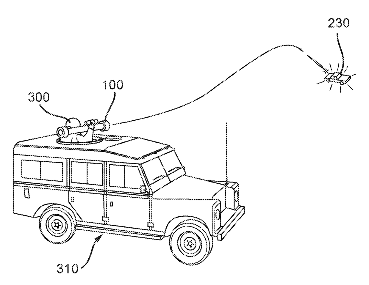
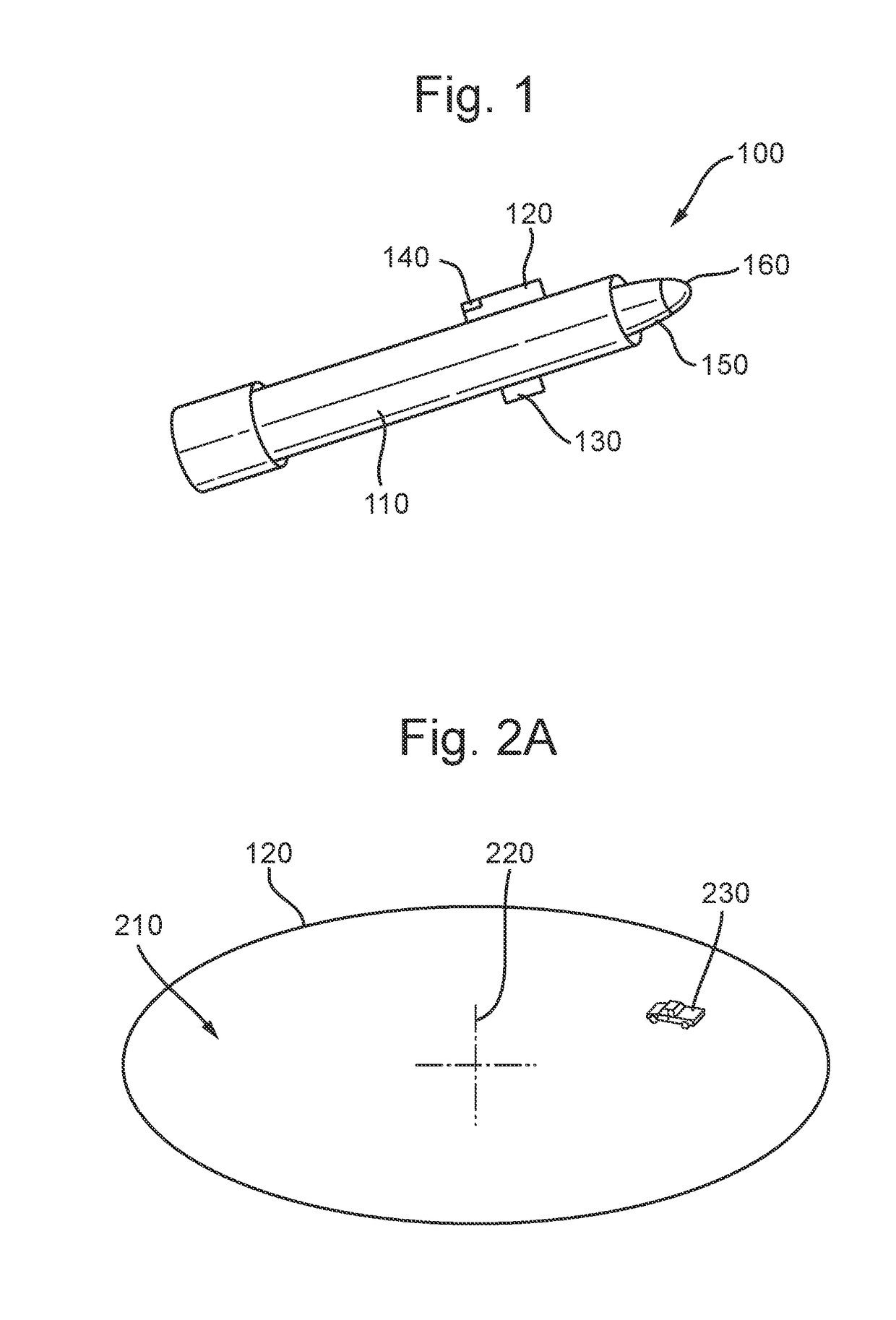
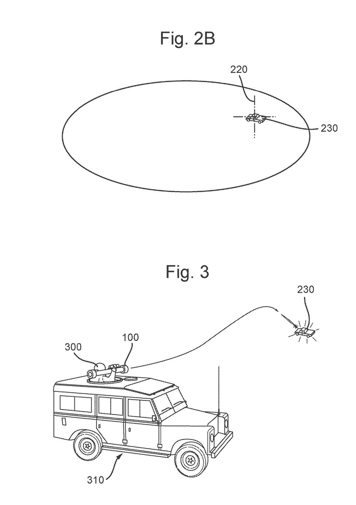
[0023]Handheld launcher 100 is illustrated in FIG. 1, and comprises launch tube 110, sight 120, and trigger 130. The launcher 100 is shown with weapon 150 mounted in tube 110 ready for launch. Launch of the weapon 150 is commenced on activation of the trigger 130 which, in the present embodiment, is a two-pull trigger. Weapon 150 is a guided weapon, and comprises a sensor cluster 160 mounted in the nose region of the weapon, as well as an on-board processor able to perform guidance algorithms such that on launch, the weapon is guided towards a target designated to it by an operator, such as target 230 (as shown ...


PUM


Abstract

A target designator for a guided weapon is disclosed. The designator has a sight arranged to display, in operation, a reticule superimposed upon a field of view. The reticule is moveable within the field of view. The designator further comprises an eye tracker operable to track the gaze of the operator whilst the operator uses the sight. The eye tracker communicates with the sight such that the reticule moves so as to be aligned with the direction of the gaze of the operator.

Description

FIELD OF THE INVENTION[0001]This invention relates to a handheld target designator for a guided weapon. More particularly, but not exclusively, the invention relates to target designators in which eye-tracking is used to designate a target to the guided weapon.BACKGROUND[0002]Guided weapons make use of sensors and guidance algorithms to guide them, once launched, towards a designated target. Occasionally, it may be possible for target designation to occur automatically (for example, the designation of an aircraft silhouetted against a clear sky), but in many cases it will be necessary for an operator to designate the target to the weapon. Currently this is done by means of a targeting reticule. In some cases the reticule may be fixed to the launcher, such that the crosshairs are permanently fixed to the boresight of the weapon. Target designation is then achieved by moving the launcher until the crosshairs are over the target. In other cases a moving reticule is provided, so that th...

Claims


Application Information

Patent Timeline
Patent Type & Authority Applications(United States)
IPC IPC(8): F41G3/02G02B27/00G06F3/01
CPCF41G3/02G02B27/0093G06F3/013F41G7/007F41G3/165F41G7/2253F41G3/225
Inventor HART, GORDON JAMESPOTTER, NATHAN REESVANCE, CHRISTOPHER JAMESTATLOCK, KERRY BENJAMINHICKS, JAMES ANDREWHINSHELWOOD, JAMES ALEXANDER DONALD
Owner MBDA UK
Why Eureka
Try Eureka