Security inspection system and method using the three-dimensional holographic imaging technology

a technology of holographic imaging and security inspection, applied in the field of millimeterwave imaging, can solve the problems of high implementation cost and low resolution of images obtained, and achieve the effects of reducing system cost, reducing the number of system parts, and simplifying the overall structur

Active Publication Date: 2018-11-08
SHENZHEN CCT THZ TECH CO LTD +1
View PDF26 Cites 3 Cited by
  • Summary
  • Abstract
  • Description
  • Claims
  • Application Information

AI Technical Summary

Benefits of technology

[0017]The aforesaid technical solution of the present disclosure only needs one millimeter-wave transceiving module and reduces the number of system parts, so the overall structure is simpler and the system cost is reduced. On the other hand, with the MISO mode of the millimeter-wa

Problems solved by technology

As can be seen from the above description, the human-body security inspection system of millimeter-wave active three-dimensional holographic imaging current available has a complicated struc

Method used


Image

  • Security inspection system and method using the three-dimensional holographic imaging technology
  • Security inspection system and method using the three-dimensional holographic imaging technology
  • Security inspection system and method using the three-dimensional holographic imaging technology

Examples


Embodiment Construction

[0025]To make objectives, technical solutions and advantages of the present disclosure clearer and easier to be understood, the present disclosure will be further described in detail hereinafter with reference to attached drawings and embodiments. It shall be appreciated that, specific embodiments described herein are only used for explaining the present disclosure and not intended to limit the present disclosure.

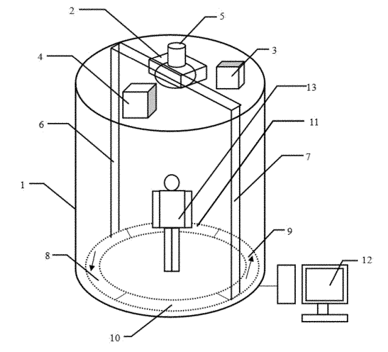
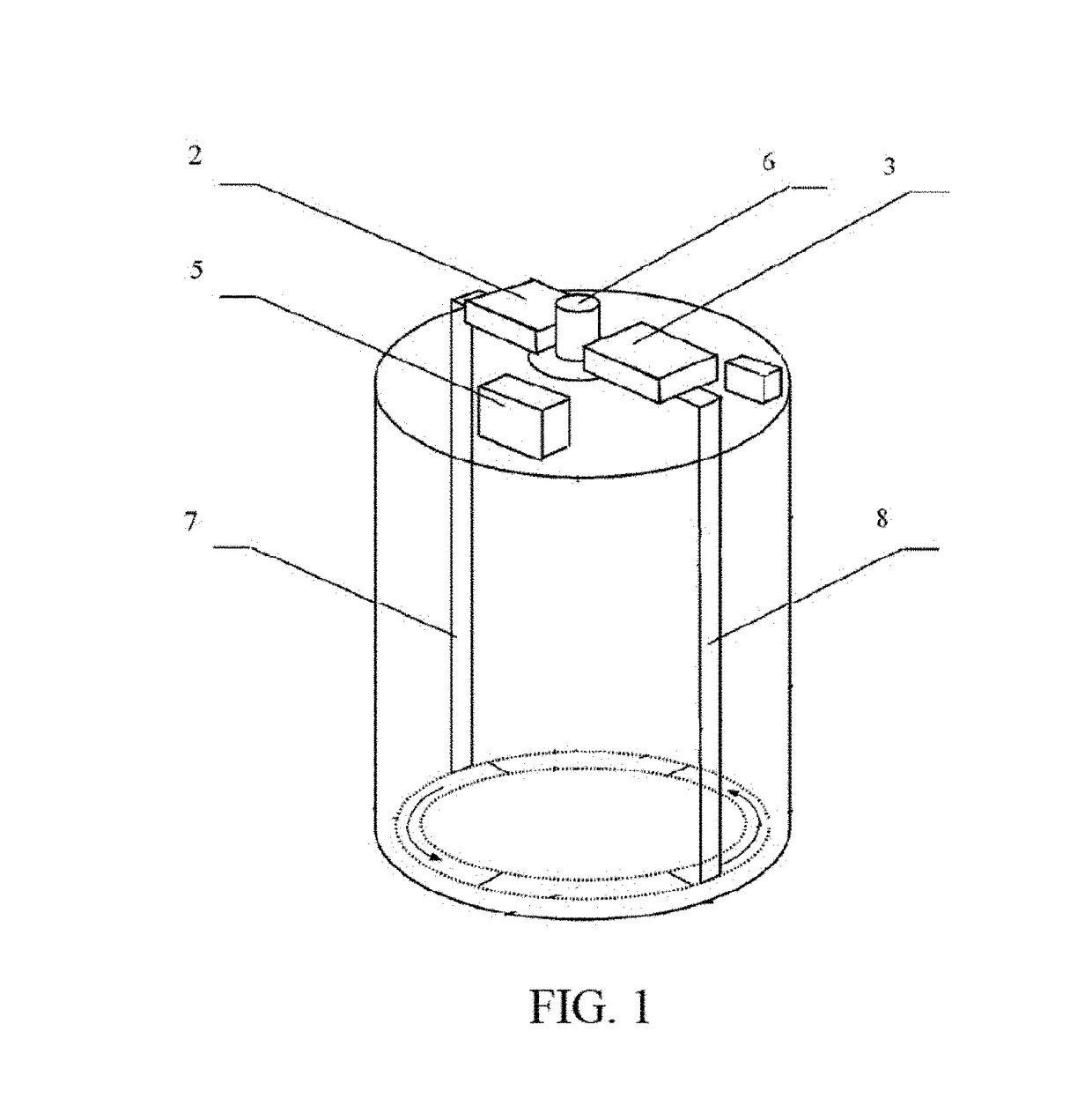
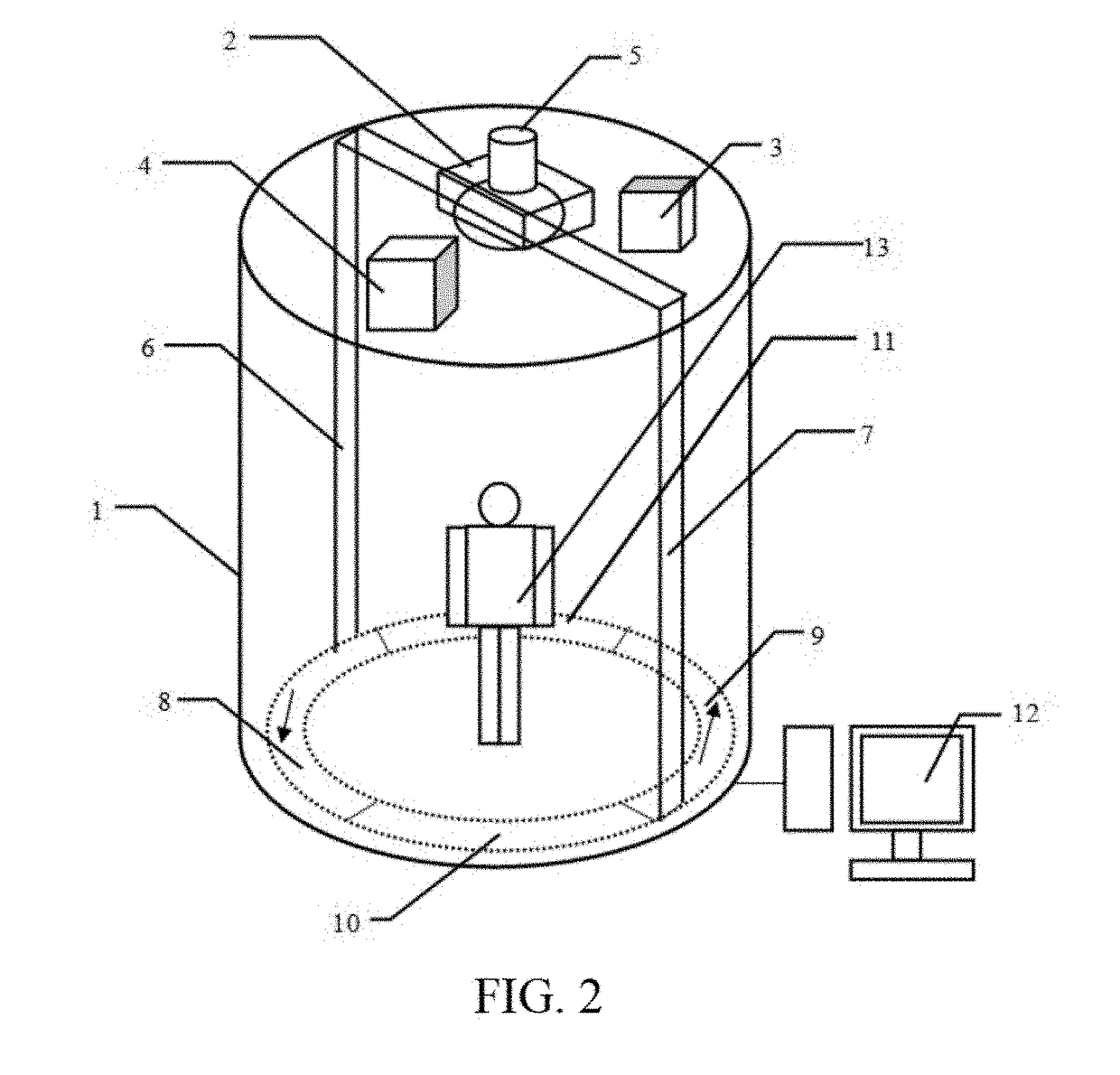
[0026]FIG. 2 is a schematic structural view of a security inspection system using the three-dimensional holographic imaging technology according to an embodiment. The security inspection system using the three-dimensional holographic imaging technology according to this embodiment comprises a body frame 1 having a to-be-scanned area 10 and at least two scan areas formed therein, and further comprises: a millimeter-wave transceiving module 2, at least two millimeter-wave switch antenna arrays, a scan driving device 5 and a parallel-image processing module 4. The number of th...


PUM


Abstract

The present disclosure relates to a security inspection system and method using the three-dimensional holographic imaging technology. The system comprises: a body frame; a millimeter-wave transceiving module, disposed on the body frame; and at least two millimeter-wave switch antenna arrays, connected with the millimeter-wave transceiving module; the number of the millimeter-wave switch antenna arrays being the same as that of the scan areas; a scan driving device, configured to drive the at least two millimeter-wave switch antenna arrays to rotate along the same direction; a control device, configured to control the scan driving device to generate a rotation angle signal; and a parallel-image processing module, configured to synthesize a three-dimensional holographic image of an under-test object according to echo signals collected by the millimeter-wave transceiving module and spatial position information of the echo signals. The present disclosure simplifies the system structure and improves the imaging resolution.

Description

CROSS-REFERENCE TO RELATED APPLICATIONS[0001]The present application is a continuation-application of International (PCT) Patent Application No. PCT / CN2016093079 filed Aug. 3, 2016, which claims foreign priority of Chinese Patent Application No. 201610262003.1, filed on Apr. 25, 2016 in the State Intellectual Property Office of China, the entire contents of which are hereby incorporated by reference.FIELD OF THE INVENTION[0002]The present disclosure generally relates to the technical field of millimeter-wave imaging, and more particularly, relates to a security inspection system and method using the three-dimensional (3D) holographic imaging technology.BACKGROUND OF THE INVENTION[0003]Frequency of a millimeter-wave ranges from 30 GHz to 300 GHz (the wavelength thereof ranges from 1 mm to 10 mm). In the electromagnetic spectrum, the location of the millimeter-wave frequency is between infrared and microwave. A millimeter-wave imaging system mainly has the following features: being se...

Claims


Application Information

Patent Timeline
IPC IPC(8): G01S13/88G01S13/90G01S7/03
CPCG01S13/887G01S13/90G01S7/03G01V8/005G01S13/9088H01Q21/00
Inventor QI, CHUNCHAOSUN, CHAOWU, GUANGSHENGZHAO, SHUKAIDING, QING
Owner SHENZHEN CCT THZ TECH CO LTD
Why Eureka
Try Eureka