
Apparatus and method for passive cooling of electronic devices

a technology for electronic devices and components, applied in the direction of transformer/inductance details, cooling/ventilation/heating modifications, transformers/inductances with temperature compensation, etc., can solve the problems of transformer assemblies and/or electrical systems to fail, and reduce the reliability of active cooling systems

Active Publication Date: 2018-11-08
GENERAL ELECTRIC CO
View PDF2 Cites 7 Cited by
  • Summary
  • Abstract
  • Description
  • Claims
  • Application Information

AI Technical Summary

Benefits of technology

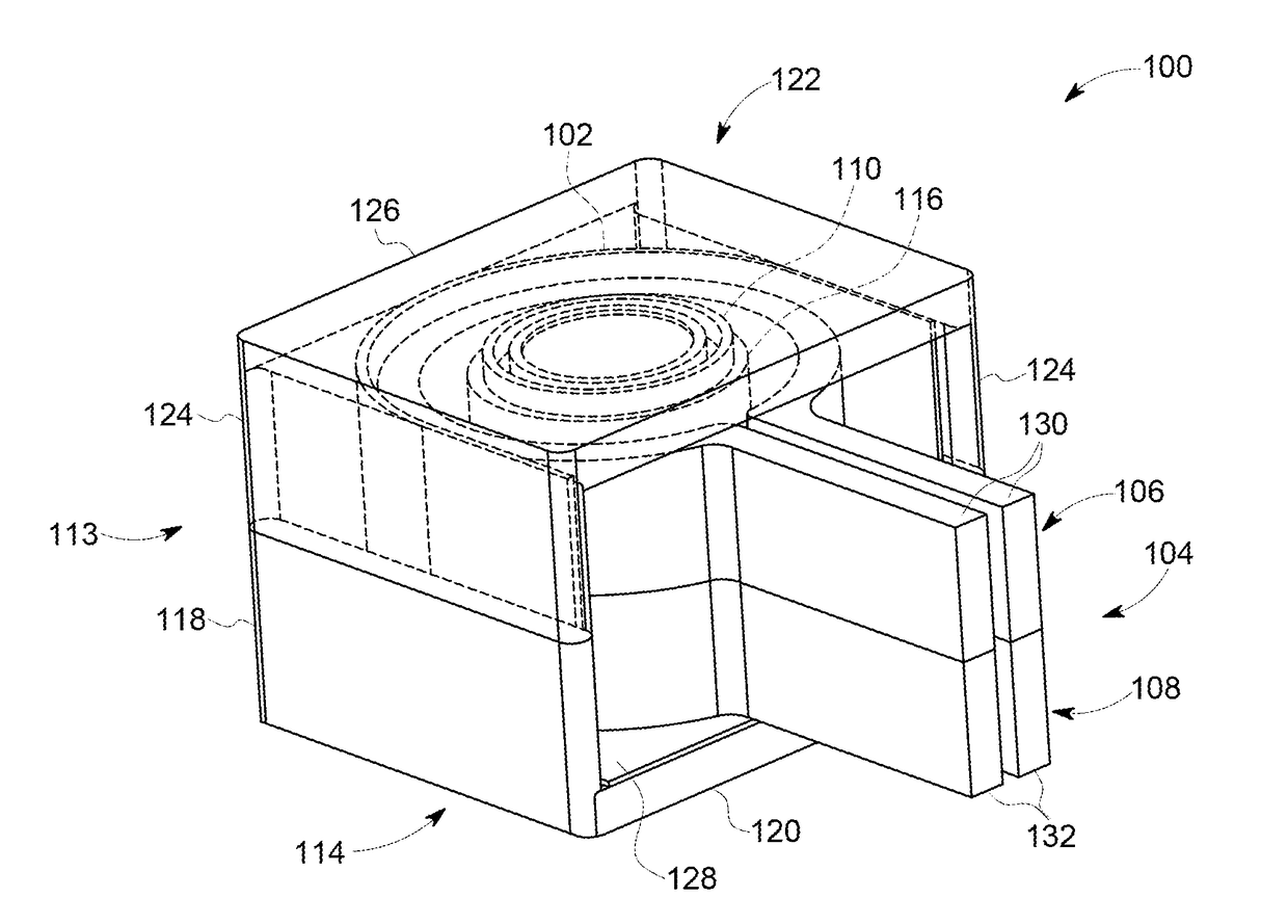
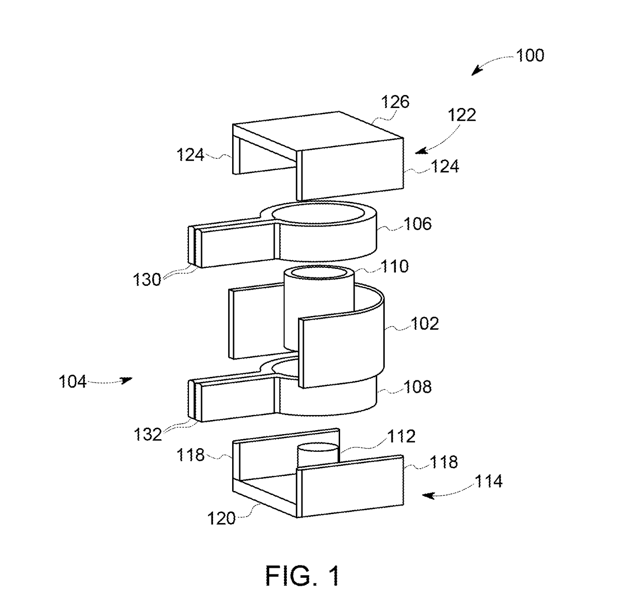
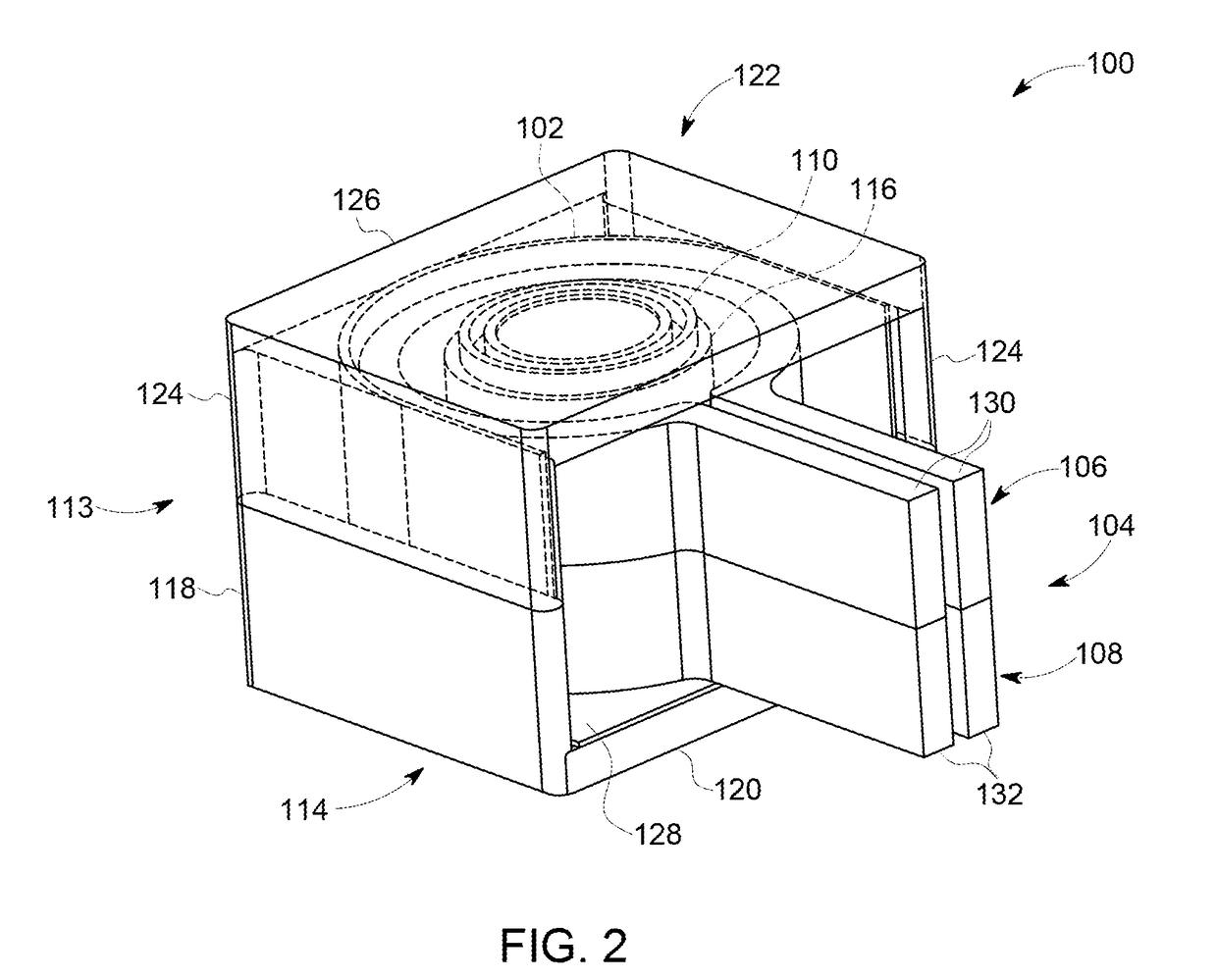
The patent describes an electronic device assembly that includes a heat dissipation member and a dielectric two-phase heat transfer device. The heat transfer device is made from a dielectric material, and it includes an evaporator region and a condenser region. The method involves using a flexible heat transfer device to transfer heat from a hot region of a component to the heat dissipation member. The technical effect of this is improved cooling of electronic devices, which can help reduce overheating and improve their performance.

Problems solved by technology

Additionally, as the design of transformer assemblies becomes more compact to fit into smaller electronic components, the heat generated by the transformer assemblies is concentrated into a smaller space, which may affect other components of the system proximate to the transformer assemblies.
In addition, the heat may impact the performance and efficiency of the transformer assemblies and / or the electrical systems.
In some instances, the heat generated by the transformer assemblies can cause the transformer assemblies and / or the electrical systems to fail.
At least some active cooling systems, however, include multiple components that can fail, which can decrease the reliability of active cooling systems, causing them to fail more easily.
In addition, active cooling systems may not operate autonomously.
The performance of at least some fans and heat sinks can be limited by the operating temperature on the transformer assemblies.
Such heat pipes and / or heat sinks configured to surround the transformer assemblies may become an additional winding in the transformer assemblies and have an induced voltage and potentially current.
In addition, such transformer assemblies can have losses in any magnetic material due to eddy currents.

Method used


Image

  • Apparatus and method for passive cooling of electronic devices
  • Apparatus and method for passive cooling of electronic devices
  • Apparatus and method for passive cooling of electronic devices

Examples


Embodiment Construction

[0017]In the following specification and the claims, reference will be made to a number of terms, which shall be defined to have the following meanings.

[0018]The singular forms “a”, “an”, and “the” include plural references unless the context clearly dictates otherwise.

[0019]Approximating language, as used herein throughout the specification and claims, is applied to modify any quantitative representation that could permissibly vary without resulting in a change in the basic function to which it is related. Accordingly, a value modified by a term or terms, such as “about”, “approximately”, and “substantially”, are not to be limited to the precise value specified. In at least some instances, the approximating language may correspond to the precision of an instrument for measuring the value. Here and throughout the specification and claims, range limitations are combined and interchanged; such ranges are identified and include all the sub-ranges contained therein unless context or lan...


PUM


Abstract

Methods and apparatuses for cooling an electronic device assembly having a heat producing are described. An electronic device assembly includes a heat dissipation member and a dielectric two-phase heat transfer device. The dielectric heat transfer device has an evaporator region thermally attached to a hot region of the heat producing component and a condenser region thermally attached to the heat dissipation member. The dielectric two-phase heat transfer device is fabricated from a dielectric material.

Description

BACKGROUND[0001]The present application relates generally to electronic devices and, more particularly, to electronic device assemblies with passive heat transfer assemblies.[0002]Some electronic device assemblies, and in particular, transformer assemblies are common electrical components used in electrical and electronic systems and provide such functions in those systems as galvanic isolation, step-down or step-up voltage or current conversion, and power conversion, among others. In addition to the use of transformer assemblies in the power loops of these systems, transformer assemblies are often used as current sensors in control applications.[0003]At least some conventional transformer assemblies generate heat when the input voltage is transformed into a desired output voltage. Additionally, as the design of transformer assemblies becomes more compact to fit into smaller electronic components, the heat generated by the transformer assemblies is concentrated into a smaller space,...

Claims


Application Information

Patent Timeline
IPC IPC(8): H01F27/18H01F27/10H01F27/20H01F27/00H05K7/20F28D15/02
CPCH01F27/18H01F27/10F28D15/02H01F27/008H05K7/20H01F27/20H01F27/22H01F27/266H01F27/306H05K7/20336H05K7/20936F28D15/0241F28D15/043
Inventor KIM, JOO HANWILLIAMS, NICHOLAS ERNESTLIU, NINGHADZIBABIC, PREDRAGHANNAFORD, LAWRENCE JOSEPH
Owner GENERAL ELECTRIC CO
Learn More