Device and method that can detect misalignment between cope and drag

a technology of misalignment and detection method, which is applied in the direction of moulding machine, foundry pattern, moulding apparatus, etc., can solve the problems of product defect, misalignment between the cope and the drag, etc., and achieve the effect of preventing consumption of molding sand due to useless molding, preventing consumption of molten metal due to useless pouring, and preventing the cause of misalignmen

Inactive Publication Date: 2018-11-15
SINTOKOGIO LTD
View PDF5 Cites 1 Cited by
  • Summary
  • Abstract
  • Description
  • Claims
  • Application Information

AI Technical Summary

Benefits of technology

[0010]The method that can detect any misalignment between the cope and the drag of a sixth aspect of the present invention is the method of the fifth aspect, wherein no molten metal is poured into the cope and the drag that have been determined to have a misalignment. By this configuration, since no molten metal is poured into the cope and drag where it has been determined that a misalignment has occurred, consumption of molten metal due to useless pouring can be prevented.
[0011]The method that can detect any misalignment between the cope and the drag of a seventh aspect of the present invention is the method of the fifth aspect, wherein if a misalignment is determined to have occurred., then a molding operation by the flaskless mol

Problems solved by technology

However, in the cope and the drag that have been manufactured by means of a flaskless molding machine and that have then been assembled, a misalignment between the cope and the d

Method used


Image

  • Device and method that can detect misalignment between cope and drag
  • Device and method that can detect misalignment between cope and drag
  • Device and method that can detect misalignment between cope and drag

Examples


first embodiment

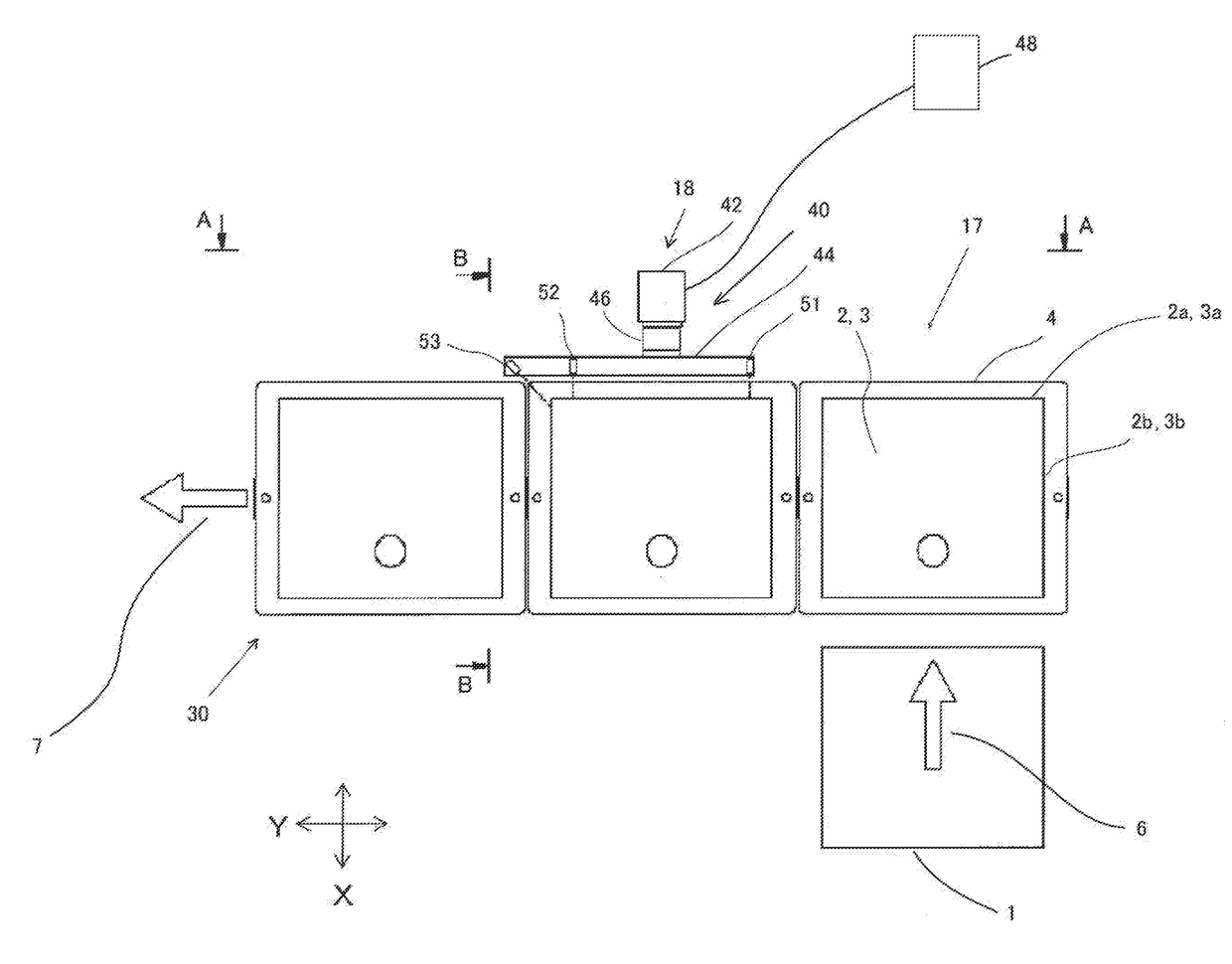
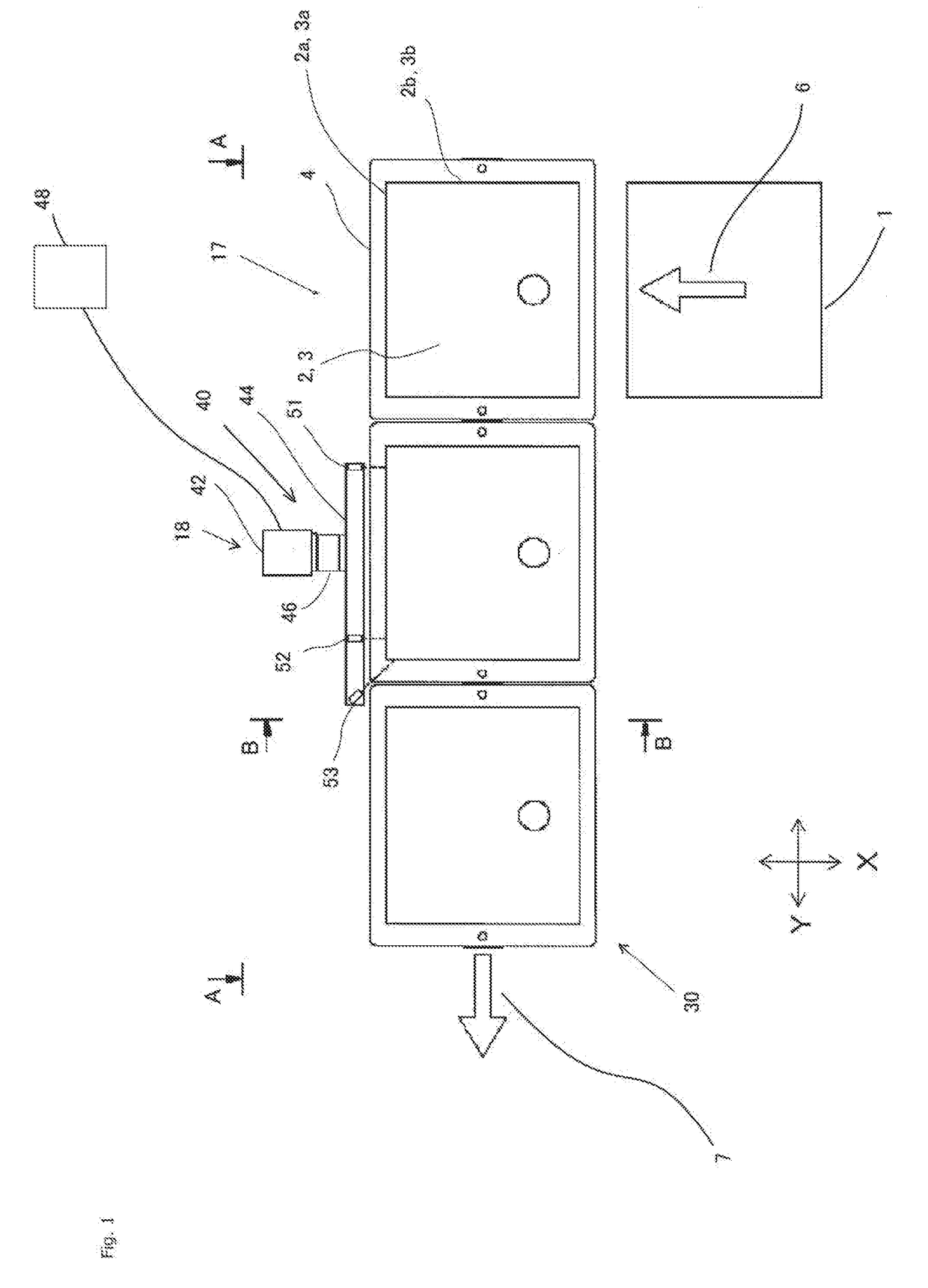
[0043]At a position adjacent to the cope 2 and the drag 3 that are intermittently conveyed, a device 40 that can detect any misalignment between the cope 2 and the drag 3 is provided. Now, the details of the device 40 that can detect any misalignment between the cope and the drag (hereafter, “device 40”), which is the present invention, are discussed. Incidentally, the direction for conveying the cope 2 and the drag 3 is called a Y-direction, the direction perpendicular to the direction for conveying the cope 2 and the drag 3 is called an. X-direction, and the vertical direction is called a Z-direction.

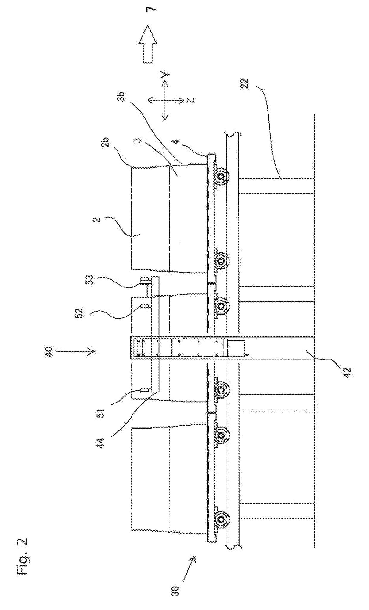
[0044]The device 40 has three means 51, 52, 53 for measuring distances to the cope and the drag (hereafter, “means 51, 52, 53”) that are arranged along the direction (the Y-direction) for conveying the cope 2 and the drag 3. The three means 51, 52, 53 are mounted on a frame 44 for moving up and down that extends along the Y-direction. The frame 44 for moving up and down moves up and d...

second embodiment

[0065]Next, with reference to FIG. 6, a device 60 that can detect any misalignment between the cope and the drag (hereafter, “the device 60”), which is a second embodiment, is discussed in detail. About the device 60, only the points that differ from the device 40 are discussed. The device 60 has a first means 71 for measuring distances to the cope, a second means 72 for measuring distances to the cope, a third means 73 for measuring distances to the cope, a first means 74 for measuring distances to the drag, a second means 75 for measuring distances to the drag, and a third means 76 for measuring distances to the drag, to measure the distances to the points 2i, 2j on the first side 2a of the cope 2, the distance to the point 2k on the second side 2b of the cope 2, the distances to the points 3i, 3j on the first side 3a of the drag 3, and the distance to the point 3k on the second side 3b of the drag 3. The first means 71 for measuring distances to the cope, the second means 72 for ...

third embodiment

[0067]Next, with reference to FIGS. 7-11, a device 5 that can detect any misalignment between the cope and drag (hereafter, “the device 5”), which is a third embodiment, is discussed. The device 5 has a first means 8 for measuring distances to the cope (hereafter, “the first means 8 for measuring”) that measures the distances to the first side 2a of the cope, which side is parallel to the Y-direction. It also has a first means 9 for measuring distances to the drag (hereafter, “the first means 9 for measuring”) that measures the distances to the first side 3a of the drag, which side is parallel to the Y-direction. The first means 8 for measuring and the first means 9 for measuring are configured to move in the Y-direction by means of a first cylinder 10, i.e., an actuator.

[0068]The device 5 also has a second means 11 for measuring distances to the drag (hereafter, “the second means 11 for measuring”) that measures the distances to the second side 2b of the drag, which side is paralle...


PUM

PropertyMeasurementUnit
Angleaaaaaaaaaa
Distanceaaaaaaaaaa

Abstract

To provide a device and a method for detecting, before pouring starts, any misalignment between a cope and a drag that have been molded by a flaskless molding machine and then assembled. The device (40) that can detect any misalignment between the cope (2) and the drag (3) that have been molded by the flaskless molding machine (1) and then assembled and that are being transported to the position for pouring comprises a plurality of means (51), (52), (53) for measuring distances to the cope and the drag that measures the distances (S11), (S12), (S13), (S21), (S22), (S23) to the cope and the drag, and a means (48) for calculating a degree of a misalignment between the cope and the drag on a basis of the distances to the cope and the drag that have been measured by the means for measuring distances to the cope and the drag.

Description

TECHNICAL FIELD[0001]The present invention relates to a device and a method that can detect any misalignment between a cope and a drag that have been manufactured by means of a flaskless molding machine and that have then been assembled.BACKGROUND ART[0002]Conventionally, a method has been known by which a cope and a drag that have been manufactured by means of a flaskless molding machine and that have then been assembled are transported and are covered with a jacket to have a weight put on them (for example, see Japanese Utility Model Publication No. H6-61363).[0003]However, in the cope and the drag that have been manufactured by means of a flaskless molding machine and that have then been assembled, a misalignment between the cope and the drag may occur while being transported or covered with the jacket. If molten metal is poured into the cope and the drag in which a misalignment occurs, a product will have a defect. This is a problem.[0004]The present invention has been developed...

Claims


Application Information

Patent Timeline
IPC IPC(8): B22C19/04B22C11/02
CPCB22C19/04B22C11/02B22C9/00B22C11/00B22D45/00B22C9/20B22C11/12
Inventor SAKAI, TSUYOSHITERABE, TOKIYASUGANUMA, YASUHITO
Owner SINTOKOGIO LTD
Why Eureka
Try Eureka