
Supercharger with a planetary gear mechanism

a technology of planetary gear mechanism and supercharger, which is applied in the direction of machine/engine, electrical control, and gearing, etc., can solve the problems of increasing pumping loss, increasing the exhaust gas pressure, and increasing the energy consumption of the battery, so as to reduce improve energy efficiency. , the effect of increasing the rotational speed of the compressor

Inactive Publication Date: 2006-02-21
HONDA MOTOR CO LTD
View PDF12 Cites 42 Cited by
  • Summary
  • Abstract
  • Description
  • Claims
  • Application Information

AI Technical Summary

Benefits of technology

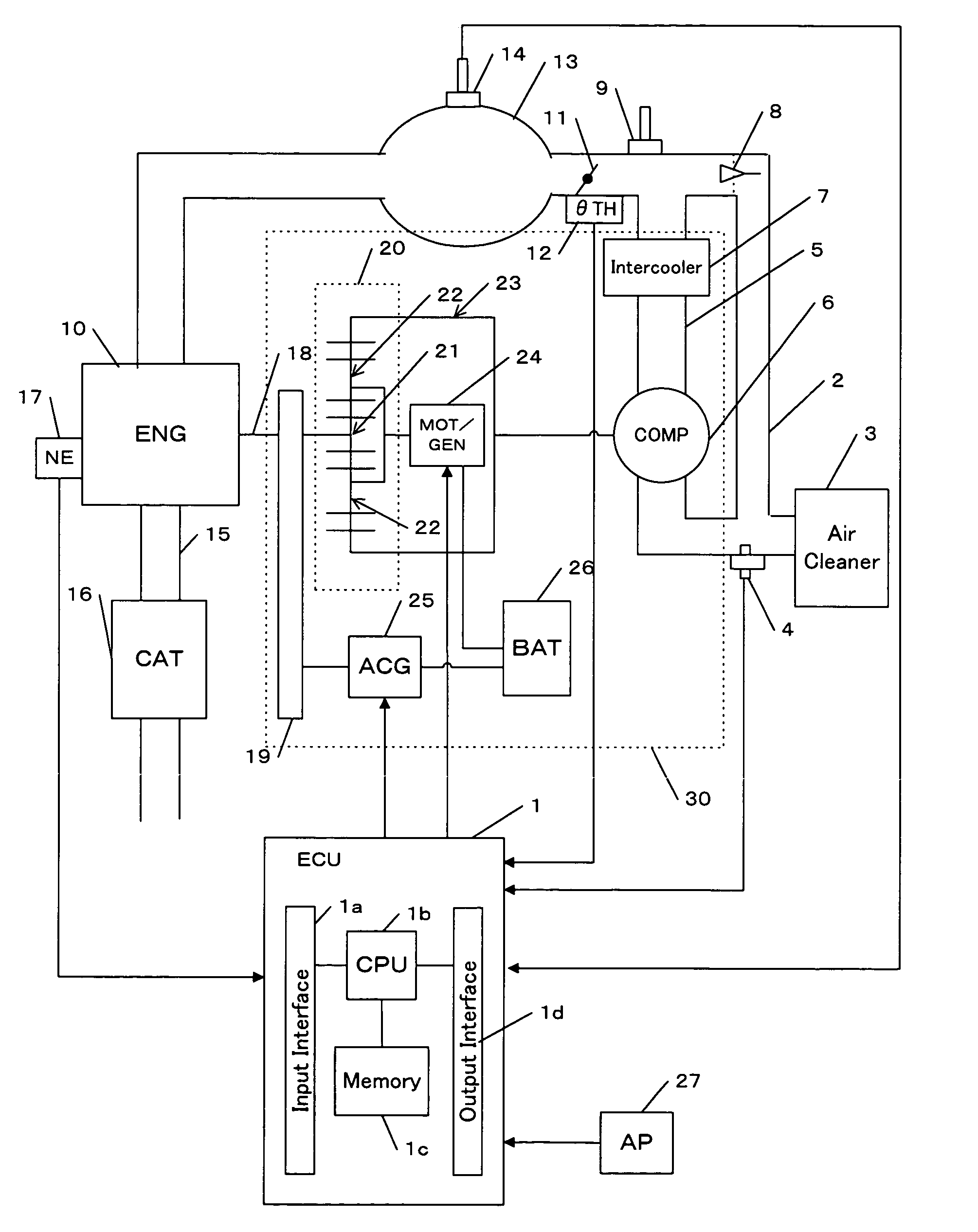
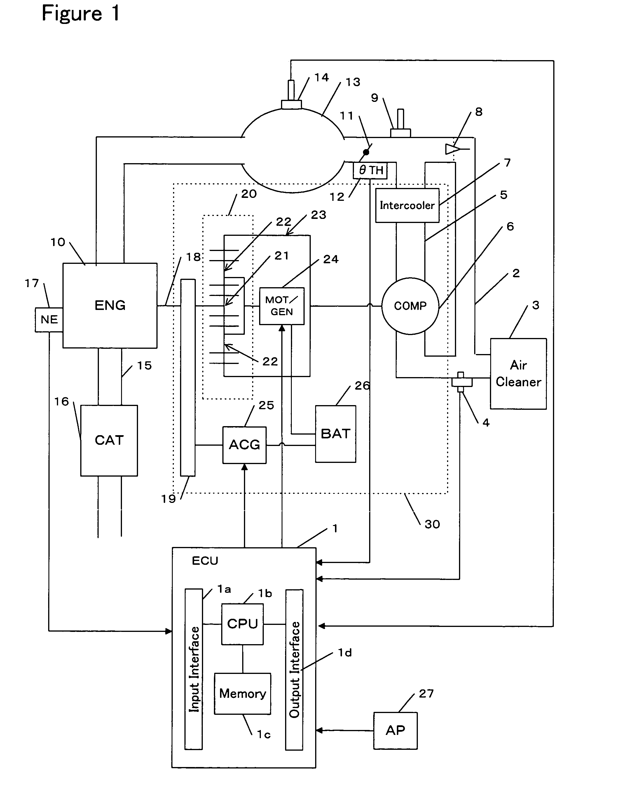
The invention is a supercharger for an engine that includes a motor / generator, a compressor, and a planetary gear mechanism. The supercharger allows for independent control of the rotational speed of the compressor, regardless of the engine's speed. This means that the desired supercharged pressure can be generated at any rotational speed of the engine. The supercharger can also adjust the amount of intake air to the engine by controlling the opening angle of the throttle valve. Additionally, a one-way clutch prevents reverse rotation of the compressor while increasing the amount of electric power generation from the motor / generator. These features improve the efficiency and responsiveness of the supercharger.

Problems solved by technology

However, the turbine provided in the exhaust system may cause a rise in the exhaust gas pressure.
If the exhaust gas pressure is high when the engine load is high, an engine knocking tends to occur and a pumping loss may increase.
When the engine load is low, the volume of exhaust gas decreases, which may lead to a shortage of the supercharged pressure.
If the exhaust gas is used for driving the turbine, the time required for activating the catalyst may be long.
However, the above problems regarding the rise in the exhaust gas pressure and the time required for activating the catalyst are not solved.
However, since rotation of the driving shaft of the engine is required, a loss of the engine output (which is referred to as a “driving loss”) may occur in accordance with an increase in the amount of supercharged air.

Method used


Image

  • Supercharger with a planetary gear mechanism
  • Supercharger with a planetary gear mechanism
  • Supercharger with a planetary gear mechanism

Examples


second embodiment

Supercharger in Accordance with a Second Embodiment

[0151]The supercharger in accordance with the first embodiment of the present invention has been described above. A supercharger in accordance with a second embodiment will be described. According to the second embodiment, a one-way clutch 36 is provided between the motor / generator 24 and the compressor 6. FIG. 19(a) shows a flow of the energy in the regeneration mode when the supercharger of the second embodiment is used. FIG. 19(b) relatively shows the rotational speed of each gear of the planetary gear mechanism 20 when the supercharger of the second embodiment is used. The one-way clutch 36 permits the compressor 6 to rotate in one direction, and locks the compressor not to rotate in the other direction. Thus, the one-way clutch 36 prevents reverse rotation of the compressor 6.

[0152]In the regeneration mode, as described above, as the amount of electric power generation becomes larger, a force braking the rotation of the compres...


PUM


Abstract

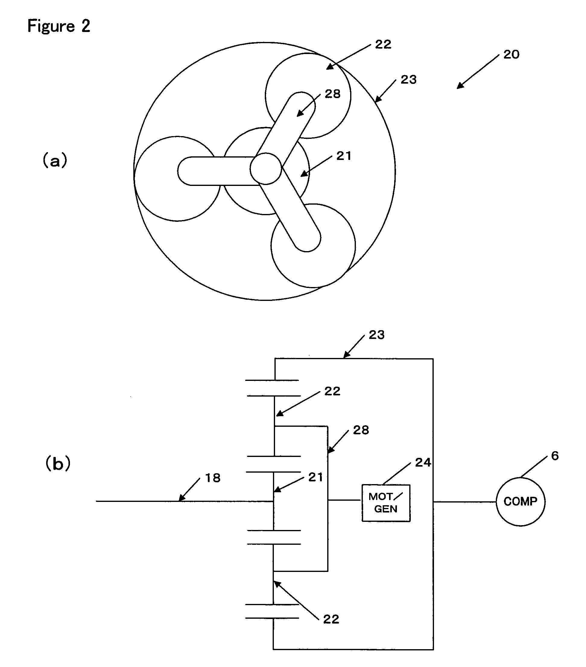
A supercharger of an engine comprises a motor / generator, a compressor provided in an air intake system of the engine, and a planetary gear mechanism. The planetary gear mechanism includes a sun gear connected to a driving shaft of the engine, planetary gears connected to the motor / generator and a ring gear connected to the compressor. The controller drives the motor / generator to control a rotational speed of the planetary gears. Through the control of the rotational speed of the planetary gears, a rotational speed of the compressor is controlled independently of a rotational speed of the engine. Thus, the rotation speed of the compressor can be continuously changed over a range from zero to a higher rotational speed than the engine rotational speed. Any desired supercharged pressure can be generated independently of the engine rotational speed.

Description

BACKGROUND OF THE INVENTION[0001]The present invention relates to a supercharger of an internal combustion engine.[0002]A supercharger of an internal combustion engine comprises a compressor for pressurizing air. The pressurized air is supplied to each cylinder of the engine. Thus, the amount of air taken into the combustion chamber of the cylinder increases, increasing the engine output.[0003]As to a supercharger, a turbocharger and a mechanical supercharger are known. According to the turbocharger, the energy of exhaust gas rotates the turbine. The turbine rotates a compressor. Such a turbocharger is disclosed in, for example, Japanese Patent Application Unexamined Publication (Kokai) No. 2002-317640. According to the mechanical supercharger, a driving shaft of an engine rotates a compressor.[0004]A motor may be used for rotating the compressor. For example, a turbocharger may comprise a motor between the turbine and the compressor. When the volume of exhaust gas is low, the motor...

Claims


Application Information

Patent Timeline
Patent Type & Authority Patents(United States)
IPC IPC(8): F02B33/00B60K1/02F16H3/44F01N3/20F02B33/32F02B39/04F02B39/10F02B39/12F02D9/02F02D13/02F02D23/00F02D29/06F02D41/00F02D41/02F02D41/04
CPCF02B39/04F02B39/10F02D13/0234F02D23/00F02D41/0007F04D25/024F02B33/32F01N3/20Y10T477/23F02D13/0207F02D13/0269F02D2041/001Y02T10/18Y02T10/144Y02T10/142F04D25/028Y02T10/12
Inventor YASUI, YUJITAMAGAWA, YUTAKA
Owner HONDA MOTOR CO LTD
Learn More