Supercharge Your Innovation With Domain-Expert AI Agents!

Mapping of metallic conductors by applying radar imaging techniques to spread spectrum time domain reflectometry returns

a radar imaging and metallic conductor technology, applied in the field of anomaly detection system, can solve the problems of high-impedance faults having a higher probability of occurrence, incidental faults have been shown to occur, and hazards for unsuspecting bystanders and utility workers

Active Publication Date: 2018-11-15
SOUTHERN CALIFORNIA EDISON
View PDF0 Cites 2 Cited by
  • Summary
  • Abstract
  • Description
  • Claims
  • Application Information

AI Technical Summary

Benefits of technology

The present invention aims to detect high-impedance faults on power lines, but it can also detect other abnormal conditions that may affect the distribution circuit. This includes signs of moved or rerouted power lines, illegal power taps, switch changes, failing equipment, and other events that cause changes to the existing map of reflections caused by impedance mismatches on the power line. The invention can help validate the accuracy and completeness of GIS maps of the distribution circuit and detect improper taps or health changes in equipment that indicate an impending failure.

Problems solved by technology

Incidental high-impedance faults are not currently detected and isolated by conventional means, such as overcurrent relays and fuses, and represent a hazard to unsuspecting bystanders and utility workers.
Incidental faults have been shown to occur at a rate of one fault per utility power line every four years.
High-impedance faults have a higher occurrence probability in longer distribution circuits.
These conditions rarely, if ever, exist under real-world conditions, where impedance discontinuities along the cable-to-load impedance mismatches are common.
When impedance measurements return unexpected values that indicate the possibility of a problem, they are referred to as impedance faults.

Method used


Image

  • Mapping of metallic conductors by applying radar imaging techniques to spread spectrum time domain reflectometry returns
  • Mapping of metallic conductors by applying radar imaging techniques to spread spectrum time domain reflectometry returns
  • Mapping of metallic conductors by applying radar imaging techniques to spread spectrum time domain reflectometry returns

Examples


Embodiment Construction

[0028]Persons of ordinary skill in the art will realize that the following description of the present invention is illustrative only and not in any way limiting. Other embodiments of the invention will readily suggest themselves to such skilled persons.

[0029]The present invention is an anomaly detection system and method using Spread-Spectrum Time-Domain reflectometry (SSTDR) techniques that can identify anomaly (high) impedances on utility power lines and determine where they are occurring.

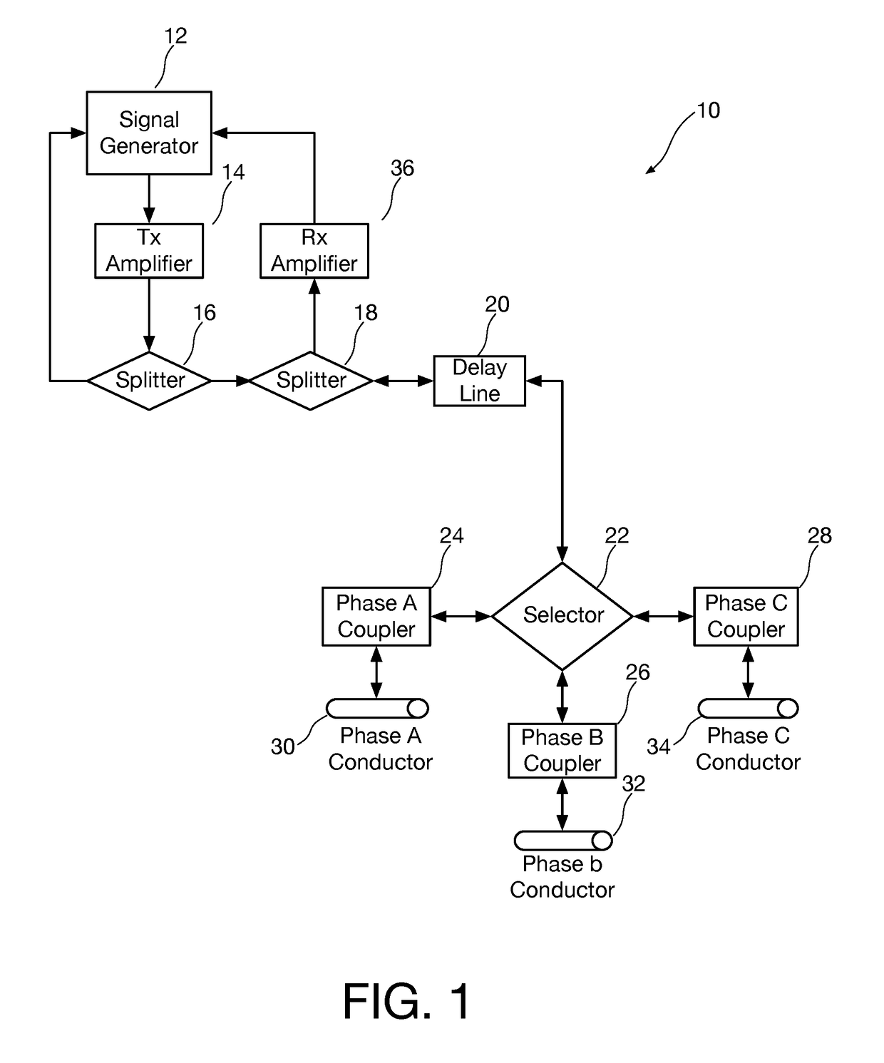
[0030]Referring first to FIG. 1, a block diagram shows an exemplary high-impedance fault detection system 10 in accordance with one embodiment of the invention. A signal generator, one non-limiting example being a software-defined radio (SDR) 12, is used for signal generation and acquisition. One non-limiting example of a signal generator suitable for use in the present invention is a PicoScope 5000.

[0031]Spread spectrum signals can also be designed in embedded controller and sent to an arbitrary...


PUM


Abstract

A method for locating an anomaly in a distribution circuit including utility power lines includes coupling a radio frequency energy source to the utility power lines, transmitting chirped radio frequency signals into the utility power lines, receiving and digitizing / analyzing signals reflected from the chirped signals by impedance mismatches caused by components and features of the distribution circuit, and generating from the digitized signals of multiple sets of the chirped radio frequency signals a reference data set identifying at least the locations of at least some of the components and features of the distribution circuit. Later sets of the chirped radio frequency signals are transmitted into the utility power lines and signals reflected from the sets of chirped signals are received and digitized and are compared with the reference data set to determine if there are anomalies on the distribution circuit.

Description

BACKGROUND[0001]The present invention relates to electrical power distribution system. More particularly, the present invention relates to an anomaly detection system using RF technology such as Spread-Spectrum Time-Domain reflectometry (SSTDR) techniques that can identify anomaly (high) impedances that represent faults on electrical distribution circuit and determine where they are occurring.[0002]Incidental high-impedance faults are not currently detected and isolated by conventional means, such as overcurrent relays and fuses, and represent a hazard to unsuspecting bystanders and utility workers. Incidental faults have been shown to occur at a rate of one fault per utility power line every four years. High-impedance faults have a higher occurrence probability in longer distribution circuits.[0003]There are high-impedance fault detection systems that use passive sensing devices to measure the primary voltage, current, and harmonics for power distribution circuits. Some of the avai...

Claims


Application Information

Patent Timeline
IPC IPC(8): G01R31/11G01R31/08
CPCG01R31/085G01R31/11
Inventor MITCHEM, SEANCASEY-SNYDER, JAKEABBOTT, BENLIU, YAXIHUFF, CHRISTOPHER M.
Owner SOUTHERN CALIFORNIA EDISON
Features
  • R&D
  • Intellectual Property
  • Life Sciences
  • Materials
  • Tech Scout
  • Unparalleled Data Quality
  • Higher Quality Content
  • 60% Fewer Hallucinations
Learn More