Voltage measurement device, voltage measurement system

a voltage measurement and voltage technology, applied in the direction of electrochemical generators, instruments, transportation and packaging, etc., can solve the problem of insufficient power supply to the electric load

Active Publication Date: 2018-11-15
AUTONETWORKS TECH LTD +2
View PDF8 Cites 3 Cited by
  • Summary
  • Abstract
  • Description
  • Claims
  • Application Information

AI Technical Summary

Benefits of technology

[0008]A power shortage while the vehicle is traveling caused by measuring the open-circuit voltage of the power storage device mounted in the vehicle is avoided.

Problems solved by technology

However, if the vehicle in which the power storage device is mounted is traveling, the power storage device is charged by an alternator provided in the vehicle, and thus a charging path from the alternator to the power storage device needs to be cut off when the open-circuit voltage is measured.
Also, because this discharging path has a portion in common with the above-mentioned charging path, there is a possibility that the supply of power to the electric load is not sufficiently performed if the charging path is simply cut off.

Method used


Image

  • Voltage measurement device, voltage measurement system
  • Voltage measurement device, voltage measurement system
  • Voltage measurement device, voltage measurement system

Examples


first embodiment

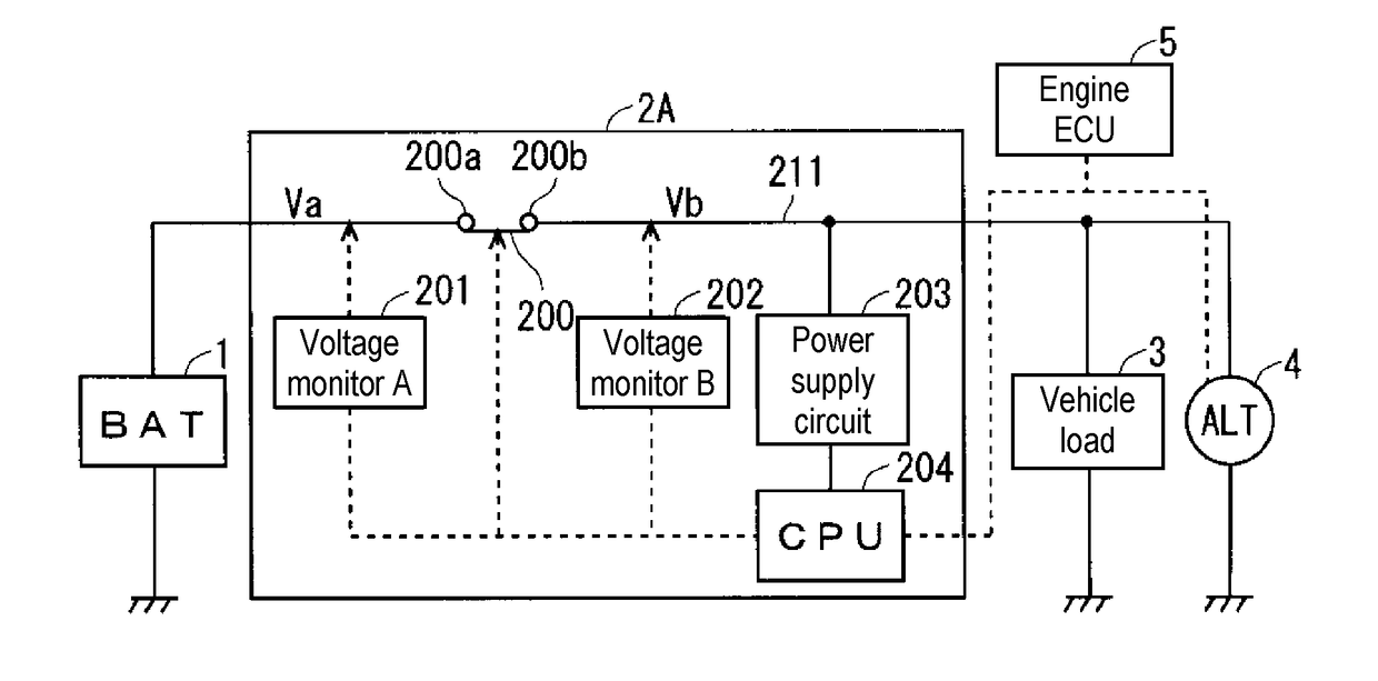
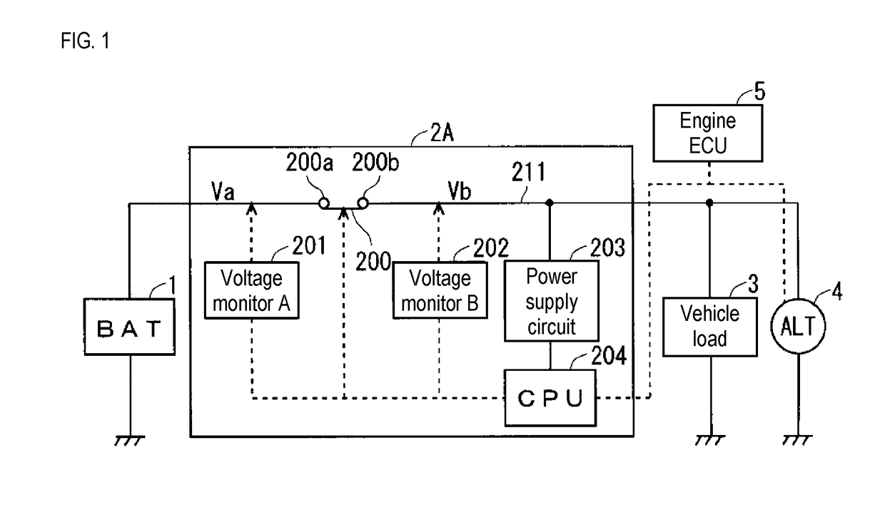
[0016]The following will describe a voltage measurement device 2A according to a FIG. 1 is a block diagram showing an example of a configuration of the voltage measurement device 2A and surroundings thereof. The voltage measurement device 2A has a function for measuring an open-circuit voltage of a power storage device 1 (in the figures, denoted as “BAT”) mounted in a vehicle. The power storage device 1 is connected to an alternator 4 (in the figures, denoted as “ALT”) via a direct current bus 211. The alternator 4 functions as an in-vehicle generator that generates electricity with rotation of an engine (not shown), and charges the power storage device 1 through the direct current bus 211 as a charging path. Normally, a positive potential is applied to the direct current bus 211. Note that, a voltage generated by the alternator 4 (generation voltage) is controlled by an ECU (Electronic Control Unit) 5 such that the voltage is set to be a predetermined voltage.

[0017]For example, th...

second embodiment

[0044]In view of this, in the second embodiment, a technology for measuring the open-circuit voltage of the power storage device 1 without cutting off the dark current even in the case where the vehicle is stopped is illustrated. Because such a technology is described, in FIG. 5, the engine ECU 5 (shown in FIG. 1) that instructs the alternator 4 to generate power at a generation voltage is omitted.

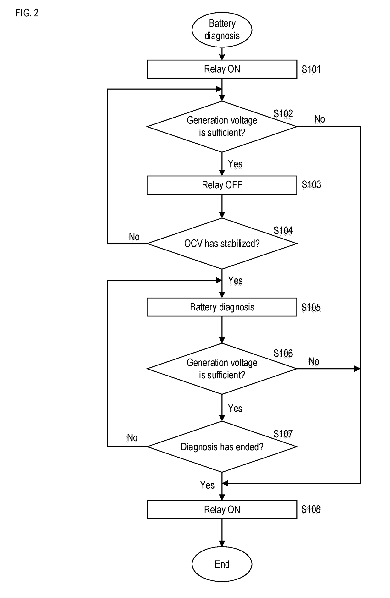
[0045]FIG. 6 is a flowchart showing an example of operations of the voltage measurement device 2C according to the second embodiment, and shows control performed by the control circuit 204. Steps S301, S303, S304, S305, S307, and S308 are respectively the same processes as steps S101, S103, S104, S105, S107, and S108 in FIG. 2.

[0046]In the second embodiment, instead of step S102 in the first embodiment, steps S302a and S302b are executed. In step S302a, as a fourth operation, the control circuit 204 determines whether or not a voltage Vc of the power storage device 206 serving as an auxili...


PUM


Abstract

A voltage measurement device includes a relay, a first voltage measurement unit, a second voltage measurement unit, a power supply circuit, and a control circuit. The power supply circuit is indirectly connected to a direct current bus. The first voltage measurement unit measures a first voltage applied to the power supply circuit. A first end of the relay is connected to the direct current bus and a second end of the relay is connected to the power storage device. The control circuit receives operating power from the power supply circuit, controls opening and closing of the relay, and closes a path between the first end and the second end when the first voltage is lower than or equal to a first threshold value. The second voltage measurement unit measures a second voltage applied to the second end at least when the relay is in an open state.

Description

CROSS-REFERENCE TO RELATED APPLICATIONS[0001]This application is the US national stage of PCT / JP2016 / 085014 filed Nov. 25, 2016 which claims priority of Japanese Patent Application No. JP 2015-233025 filed Nov. 30, 2015.TECHNICAL FIELD[0002]This present invention relates to a voltage measurement device, and more particularly, to a technology for measuring an open-circuit voltage of an in-vehicle power storage device.BACKGROUND ART[0003]In order to diagnose a power storage device mounted in a vehicle (including a so-called battery or electric double-layer capacitor), it is known to use measurement of an internal resistance. For example, JP 2014-230343A discloses a technology in which a main battery and a sub battery are provided together, and the internal resistance of the sub-battery is measured using the current value and the voltage value at the time at which a smoothing capacitor is charged by the sub-battery.[0004]It is also known that, when diagnosing the power storage device, ...

Claims


Application Information

Patent Timeline
Patent Type & Authority Applications(United States)
IPC IPC(8): G01R31/36B60R16/04B60R16/033H02J7/00H02J7/14
CPCG01R31/362B60R16/04B60R16/033H02J7/0047H02J7/14H01M10/48G01R31/3835Y02T10/70Y02E60/10H02J7/0048
Inventor YASUNORI, HIROMICHI
Owner AUTONETWORKS TECH LTD
Why Eureka
Try Eureka