
System and method for interactive demand response in energy generation and routing

a demand response and energy generation technology, applied in the direction of electric variable regulation, process and machine control, instruments, etc., can solve the problems of large electricity consumption, limited customer options, and current demand response systems that do not allow customers to dynamically tailor their power

Active Publication Date: 2018-11-15
VALMONT INDUSTIES INC
View PDF12 Cites 4 Cited by
  • Summary
  • Abstract
  • Description
  • Claims
  • Application Information

AI Technical Summary

Benefits of technology

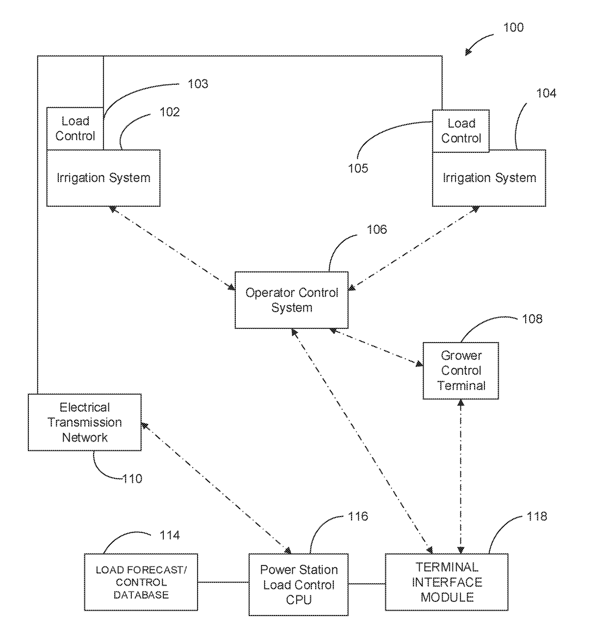
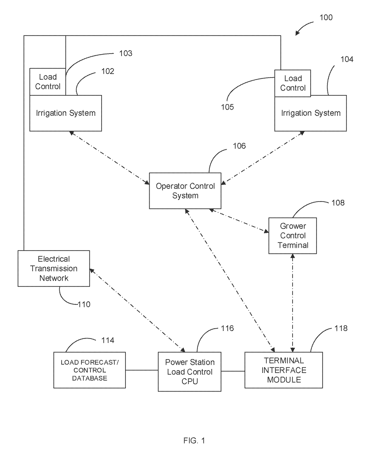
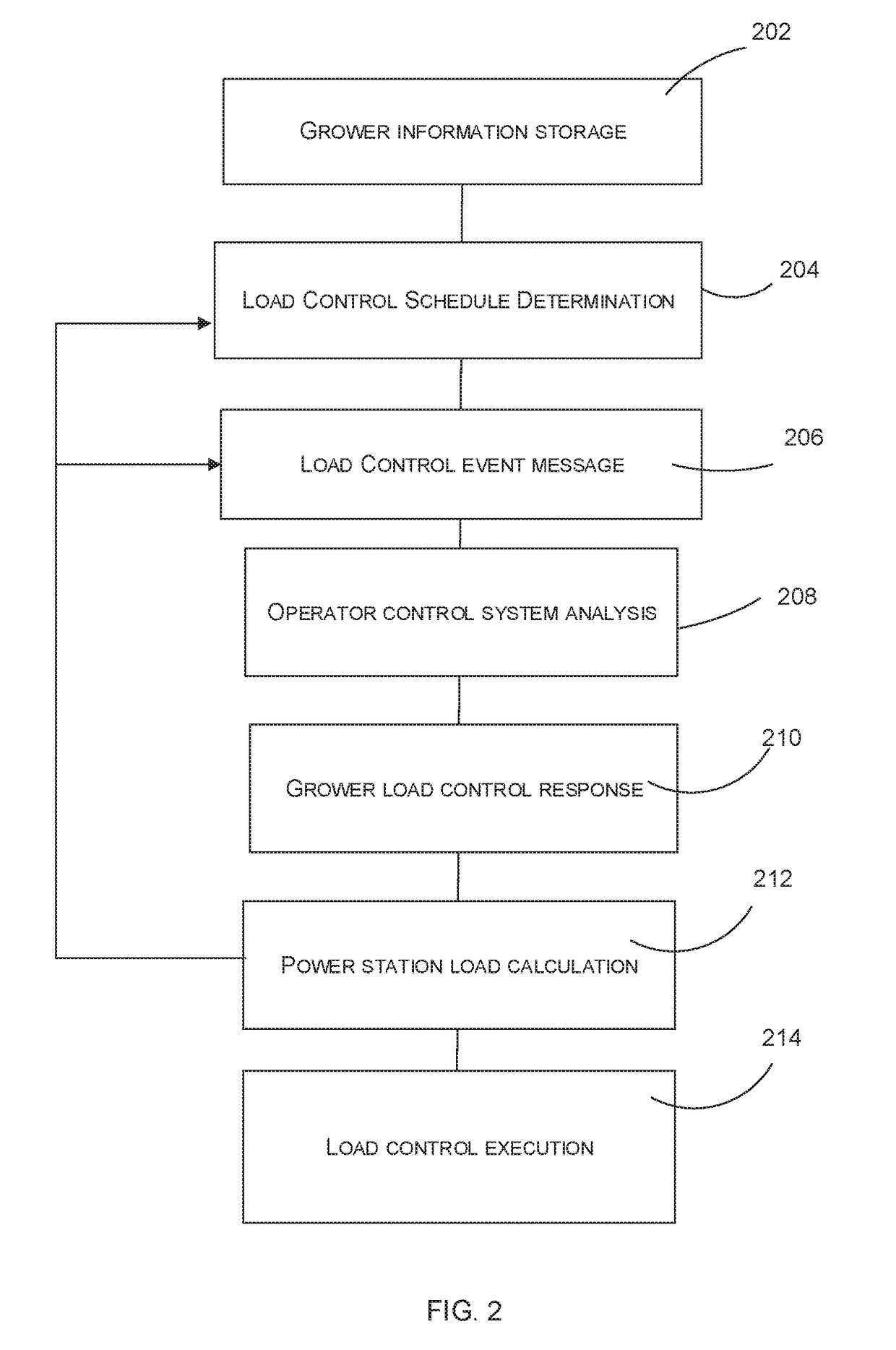
The present invention is an interactive demand response system for controlling and routing power to irrigation systems. The system includes a power station load control CPU and a terminal interface module that allows growers to sign up for and selectively override load control events. The system also sends automated text and email alerts for upcoming load control events, displays current system demand within groups of load control devices, and creates and sends messages and reports to the power company and growers. The technical effects of this invention include improved load control automation and efficiency, reduced power usage, and increased flexibility for growers in managing power usage.

Problems solved by technology

Within conventional demand response systems, a customer's options are limited to either adjusting power demand by postponing some tasks that require large amounts of electric power, or paying a higher price for their electricity.
Regardless of how they are setup, current demand response systems do not allow customers to dynamically tailor their power consumption based on rapid fluctuations in temperature or other factors.
This limitation is particularly important to farm operations which consume large amounts of electricity within very concentrated windows of time.

Method used


Image

  • System and method for interactive demand response in energy generation and routing
  • System and method for interactive demand response in energy generation and routing
  • System and method for interactive demand response in energy generation and routing

Examples


Embodiment Construction

[0010]For the purposes of promoting an understanding of the principles of the present invention, reference will now be made to the embodiments illustrated in the drawings and specific language will be used to describe the same. It will nevertheless be understood that no limitation of the scope of the present invention is hereby intended and such alterations and further modifications in the illustrated devices are contemplated as would normally occur to one skilled in the art.

[0011]Various inventive features are described below which can be used independently of one another or in combination with other features. However, any single inventive feature may not address any of the problems discussed above or only address one of the problems discussed above. Further, one or more of the problems discussed above may not be fully addressed by any of the features described below.

[0012]The terms “program,”“computer program,”“software application,”“module” and the like as used herein, are define...


PUM


Abstract

The present invention provides an interactive demand response system for controlling and routing power to one or more irrigation systems. According to a preferred embodiment of the present invention, a system is provided which includes a power station load control CPU and a terminal interface module to allow growers to sign up for and selectively override load control events via any web-connected computer, tablet, or smartphone. Further, the present invention preferably generates automated text and email alerts for upcoming load control events including the start and end times for each event. Further, the present invention may provide for displays of current system demand within groups of load control devices before, during, and after load control events. Further the system of the present invention preferably includes the creation and transmission of messages and reports which provide a recap for the power company and / or the growers and which detail the level of participation, power usage, timing of load control events, and the selection of overrides.

Description

RELATED APPLICATIONS[0001]The present application claims priority to U.S. Provisional Application No. 62 / 505,215 filed May 12, 2017.BACKGROUND AND FIELD OF THE PRESENT INVENTION1. Field of the Present Invention[0002]The present invention relates generally to a system and method for providing interactive demand response in energy generation and routing and more particularly, to a system and method for providing an interactive demand response system for controlling and routing power to one or more irrigation systems.2. Background of the Invention[0003]Demand response is a forced reduction in the power consumption of an electric utility customer to better match the demand for power with the supply. Demand response is used by power companies to reduce the load on their systems. This is generally accomplished by remote management of a control box and a local load control switch that is wired into electrical systems of equipment to enable shutting down equipment during periods of peak dem...

Claims


Application Information

Patent Timeline
Patent Type & Authority Applications(United States)
IPC IPC(8): G05F1/66A01G25/16
CPCG05F1/66A01G25/16G08C17/02H04L67/125Y04S40/18H02J13/00001H02J13/00022H02J13/00028H02J3/14H02J3/003Y04S40/128Y04S40/126Y02B90/20Y02B70/3225Y04S20/222
Inventor HOHM, JESSEMEYER, MICHAEL D.
Owner VALMONT INDUSTIES INC
Learn More