Electrically conductive oxide sintered compact, member for electrical conduction, gas sensor, piezoelectric element, and method for producing piezoelectric element

Active Publication Date: 2018-11-15
NGK SPARK PLUG CO LTD
View PDF4 Cites 1 Cited by
  • Summary
  • Abstract
  • Description
  • Claims
  • Application Information

AI Technical Summary

Benefits of technology

[0011]The present inventors have found that the conductive oxide sintered compact as disclosed in Patent Document 4 is still susceptible to improvement. In the case of forming a sintered compact of conductive oxide on an oxide substrate, for example, it is desirable that the firing temperature of the conductive oxide can be freely selected depending on the material of the substrate, the production conditions of the ceramic product etc. More specifically, there is a case where a low firing temperature of the order of 1100° C. is desirable for the secondary firing of a conductive oxide on a sintered substrate of oxide. By such low temperature firing at about 1100° C., the reaction between the oxide as the material of the substrate and the conductive oxide can be reduced or suppressed so as to decrease the possibility t

Problems solved by technology

However, the firing of Ni, Cu, W with the ceramic substrate requires atmosphere control that makes it difficult to attain the intended performance of the ceramic substrate and results in high production cost.
On the other hand, the melting point of Ag is low (962° C.) so that not only the material of the ceramic substrate applicable becomes limited, but also the properties of the ceramic substrate may be impaired by low-temperature firing.
Further, noble metals such as Pd, Ir and Pt are expensive so that it is difficult to use these noble metals for electrode applications where large areas are required.
However, the conductive oxides as disclos

Method used


Image

  • Electrically conductive oxide sintered compact, member for electrical conduction, gas sensor, piezoelectric element, and method for producing piezoelectric element
  • Electrically conductive oxide sintered compact, member for electrical conduction, gas sensor, piezoelectric element, and method for producing piezoelectric element
  • Electrically conductive oxide sintered compact, member for electrical conduction, gas sensor, piezoelectric element, and method for producing piezoelectric element

Examples


Example

[0032]A. Composition of Electrically Conductive Oxide Sintered Compact

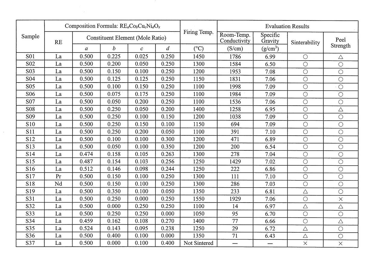
[0033]An electrically conductive oxide sintered compact according to one embodiment of the present invention is in the form of an oxide sintered compact containing a crystal phase that has a perovskite oxide crystal structure represented by the following composition formula:

RE1CobCucNidOx   (1)

where RE is a rare-earth element; a+b+c+d=1; and 1.25≤x≤1.75.

[0034]Herein, the values of the respective parameters a, b, c and d respectively satisfy the following conditions.

0.474≤a≤0.512   (2a)

0.050≤b≤0.350   (2b)

0

0.050≤d≤0.350   (2d)

[0035]As the rare-earth element RE, one or more kinds of various rare-earth elements such as La, Ce, Pr, Nd, Pm and Sm may be contained. It is preferable to contain one or more of La, Pr and Nd as the rare-earth element RE. In order for the electrically conductive oxide sintered compact to show a higher room-temperature conductivity, it is particularly preferable to contain only...


PUM

PropertyMeasurementUnit
Temperatureaaaaaaaaaa
Electrical conductivityaaaaaaaaaa

Abstract

An electrically conductive oxide sintered compact according to one embodiment of the present invention includes a crystal phase that has a perovskite oxide crystal structure represented by the composition formula: REaCobCucNidOx where RE is a rare-earth element; a+b+c+d=1; and 1.25≤x≤1.75, wherein the values of a, b, c and d respectively satisfy the following conditions: 0.474≤a≤0.512; 0.050≤b≤0.350; 0≤c≤0.250; and 0.050≤d≤0.350.

Description

FIELD OF THE INVENTION[0001]The present invention relates to an electrically conductive oxide sintered compact and to an electrical conduction member, a gas sensor and a piezoelectric element, each of which utilizes the electrically conductive oxide sintered compact, and a method for producing the piezoelectric element.BACKGROUND ART[0002]A ceramic product as an electronic component has a ceramic substrate and an electrode generally formed of metal on the ceramic substrate. Examples of such a ceramic product are a laminated ceramic capacitor with a Ni electrode, Pd electrode or Pt electrode, a LTCC (low temperature co-fired ceramic) component with a Ag electrode, Cu electrode or Ag-Pd electrode, a piezo actuator with a Pd electrode, a semiconductor package with a W electrode, and a spark plug with a Ir electrode or a Pt electrode.[0003]However, the firing of Ni, Cu, W with the ceramic substrate requires atmosphere control that makes it difficult to attain the intended performance of...

Claims


Application Information

Patent Timeline
IPC IPC(8): H01B1/08C04B35/468C04B35/49C04B35/50G01N27/407G01N29/24
CPCH01B1/08C04B35/4682C04B35/49C04B35/50G01N27/4073G01N29/2437C04B2235/3201C04B2235/3208C04B2235/604G01N2291/0255G01N29/022C04B2235/3203C04B2235/762G01N2291/0256G01N2291/0426
Inventor KOZUKA, HISASHIOKIMURA, YASUYUKIOHBAYASHI, KAZUSHIGE
Owner NGK SPARK PLUG CO LTD
Why Eureka
Try Eureka