Printing and thermal activation method and device for a heat-sensitive adhesive sheet

US20060082638A1Inactive Publication Date: 2006-04-20SEIKO INSTR INC

Image

  • Printing and thermal activation method and device for a heat-sensitive adhesive sheet
  • Printing and thermal activation method and device for a heat-sensitive adhesive sheet
  • Printing and thermal activation method and device for a heat-sensitive adhesive sheet

Examples


Embodiment Construction

[0042] Hereinafter, embodiments of the present invention will be described with reference to the accompanying drawings.

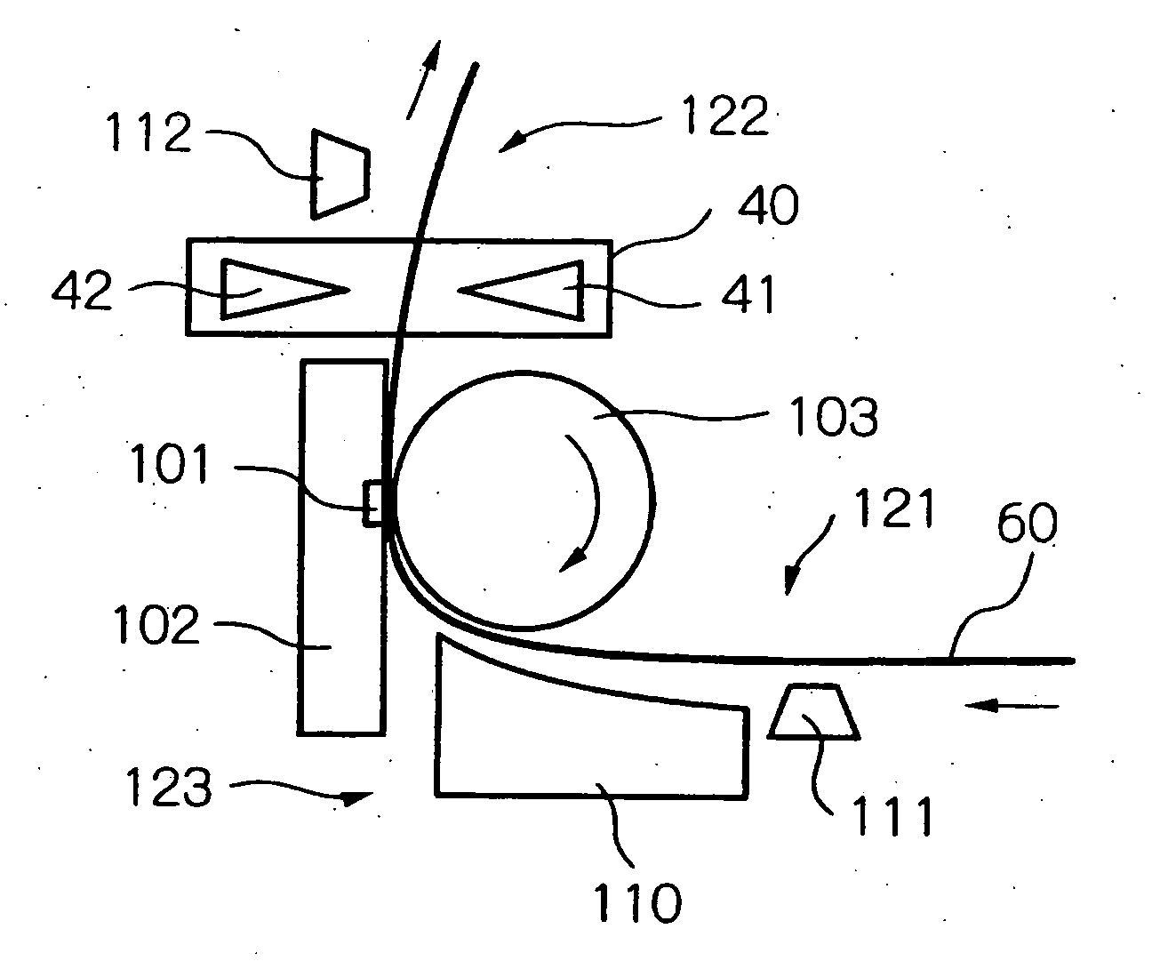
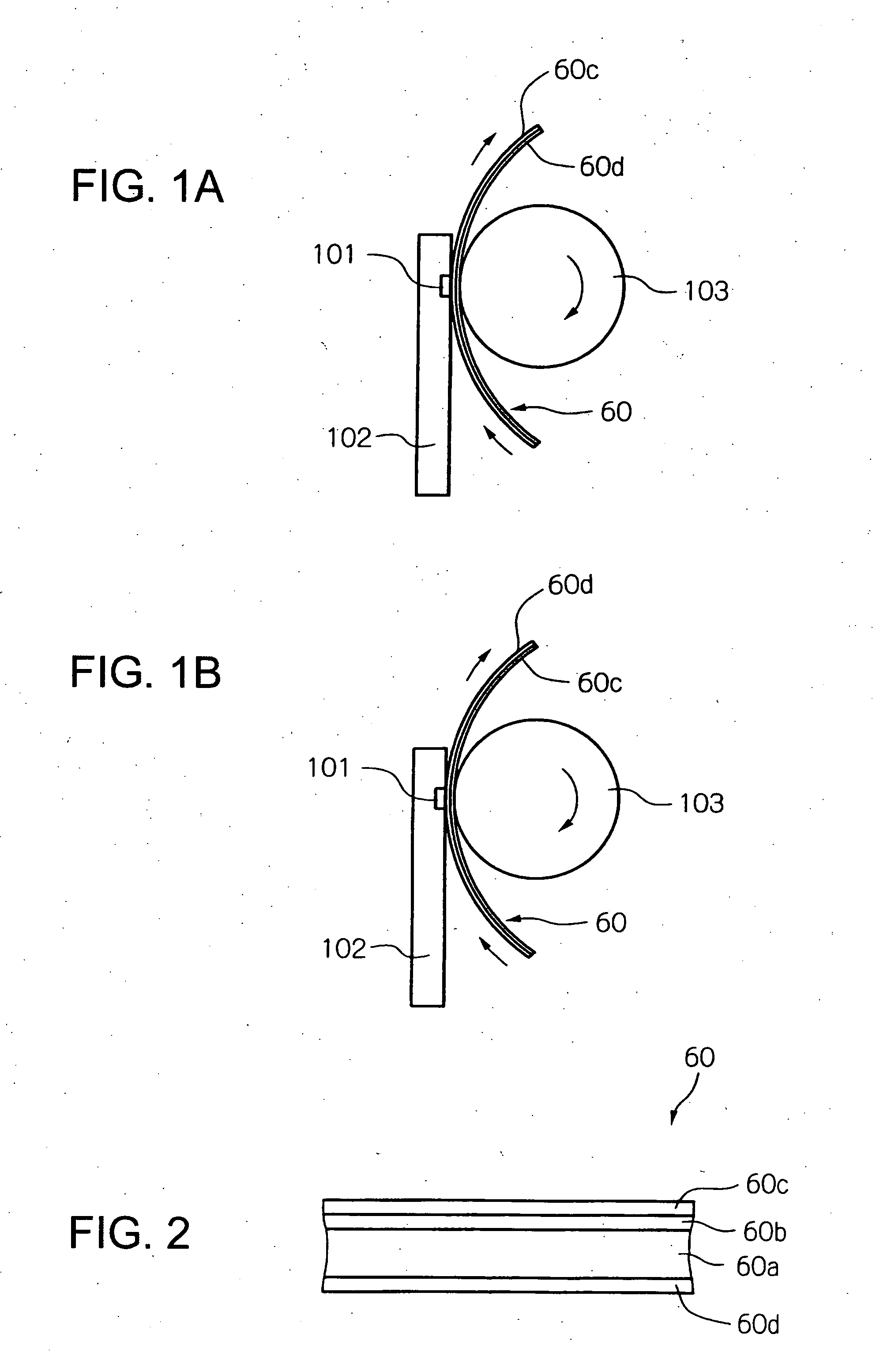
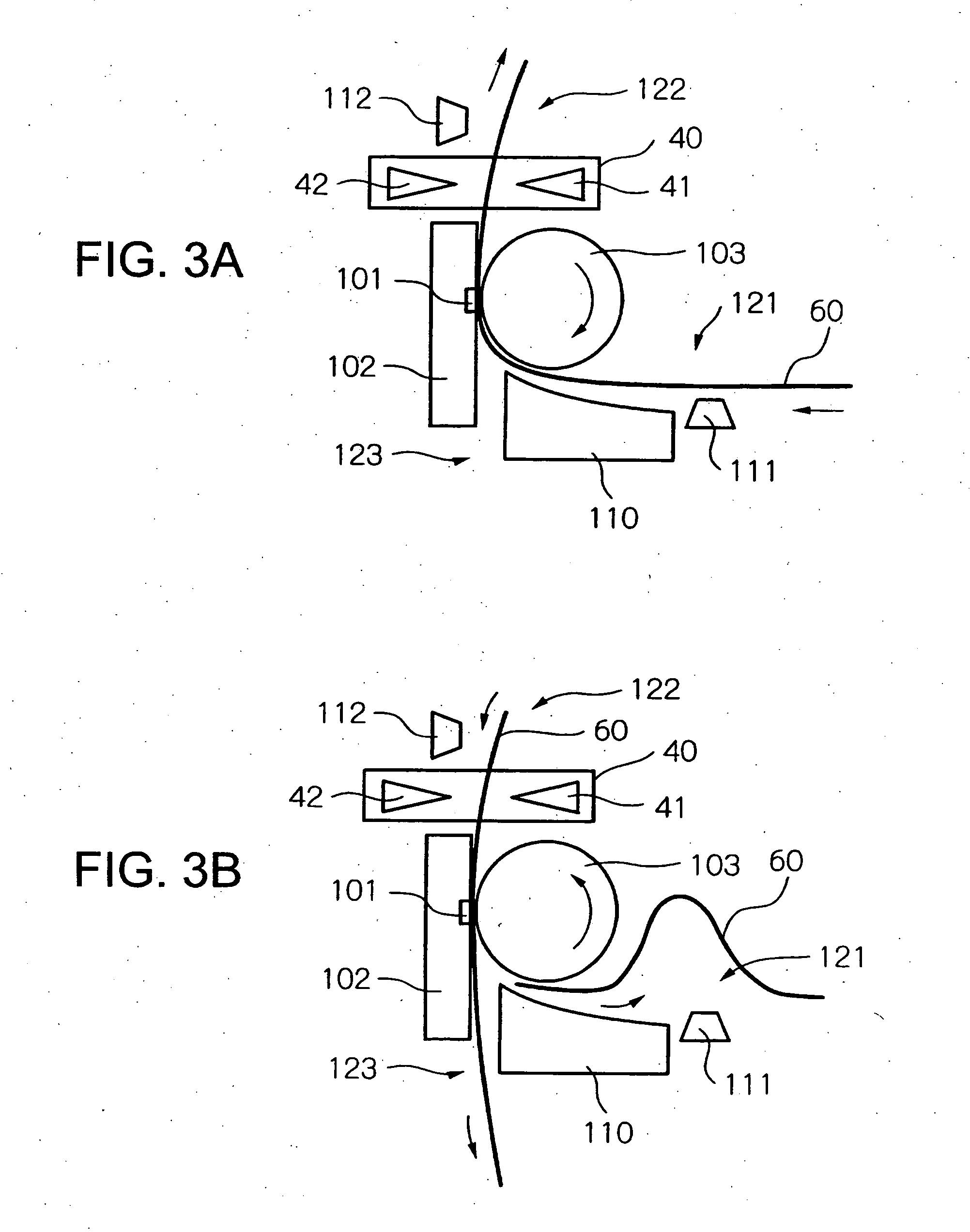
[0043]FIGS. 1A and 1B are schematic diagrams showing the most basic structure of a printing and thermal activation device for a heat-sensitive adhesive sheet 60 according to the present invention. As shown in FIG. 2, the heat-sensitive adhesive sheet 60 has, although not particularly limited to, a structure where a heat-insulating layer 60b and a heat-sensitive color-developing layer (printable layer) 60c are formed on a front side of a sheet base material 60a while a heat-sensitive adhesive is applied and dried to form a heat-sensitive adhesive layer 60d on its rear side. Note that the heat-sensitive adhesive layer 60d is formed with a heat-sensitive adhesive mainly containing a thermoplastic resin, a solid plastic resin, or the like. Further, the heat-sensitive adhesive sheet 60 may dispense with the heat-insulating layer 60b or have a protective layer or colored...


PUM


Abstract

Provided is a printing and thermal activation device for a heat-sensitive adhesive sheet that is compact, lightweight, and simple in structure. The heat-sensitive adhesive device for a heat-sensitive adhesive sheet includes a thermal head capable of printing on a printable layer and thermal activation for a heat-sensitive adhesive layer. When the heat-sensitive adhesive sheet is inserted, a platen roller and the thermal head are operated to transport the heat-sensitive adhesive sheet while printing on the printable layer. The heat-sensitive adhesive sheet is cut with a cutter unit at a predetermined position and then the cut sheet passes through a transporting roller pair and is guided to a reversing mechanism. The heat-sensitive adhesive sheet makes almost one rotation on an outer periphery of a reversing roller and is reversed, and then is transported by the transporting roller pair and the platen roller starting reverse rotation while the heat-sensitive adhesive layer is thermally activated with the thermal head.

Description

BACKGROUND OF THE INVENTION [0001] 1. Field of the Invention [0002] The present invention relates to a printing and thermal activation method and device for a heat-sensitive adhesive sheet having a printable layer on one side and a heat-sensitive adhesive layer on the other side. [0003] 2. Description of the Related Art [0004] In recent years, most of commonly used sticker labels as barcode labels or price stickers are such that a heat-sensitive adhesive layer is formed on an opposite side of a recording surface (printable layer) and release paper (separator) is stuck and temporarily bonded onto the heat-sensitive adhesive layer when in storage. However, this type of sticker label is disadvantageous in that the release paper needs to be peeled off from the heat-sensitive adhesive layer before use in label form, which inevitably involves wastes. [0005] To cope with this, there have been developed as a release-paper-free system, a heat-sensitive adhesive label having a sheet-like base...

Claims


Application Information

Patent Timeline
20 Apr 2006
Publication
US20060082638A1
IPC
B41J2/325
CPC
B41J2/325
Inventors
SANBONGI, NORIMITSU; HOSHINO, MINORU