

Multifunctional air pump
a multi-functional, air-pump technology, applied in the direction of machines/engines, mechanical devices, liquid fuel engines, etc., can solve the problems of affecting user comfort, mattress may leak air over time, and become softer and softer
- Summary
- Abstract
- Description
- Claims
- Application Information
AI Technical Summary
Benefits of technology
Problems solved by technology
Method used
Image

Examples
first embodiment
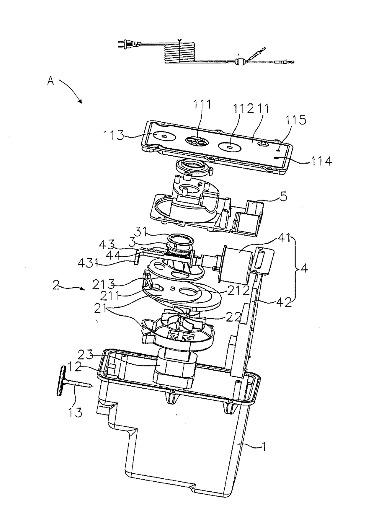
[0057]Referring next to FIGS. 3-8, the air pump assembly A is shown and includes a seat or housing 1, an air pump 2 located within the housing 1, a moveable air core 3, and an automatic operation mechanism 4.
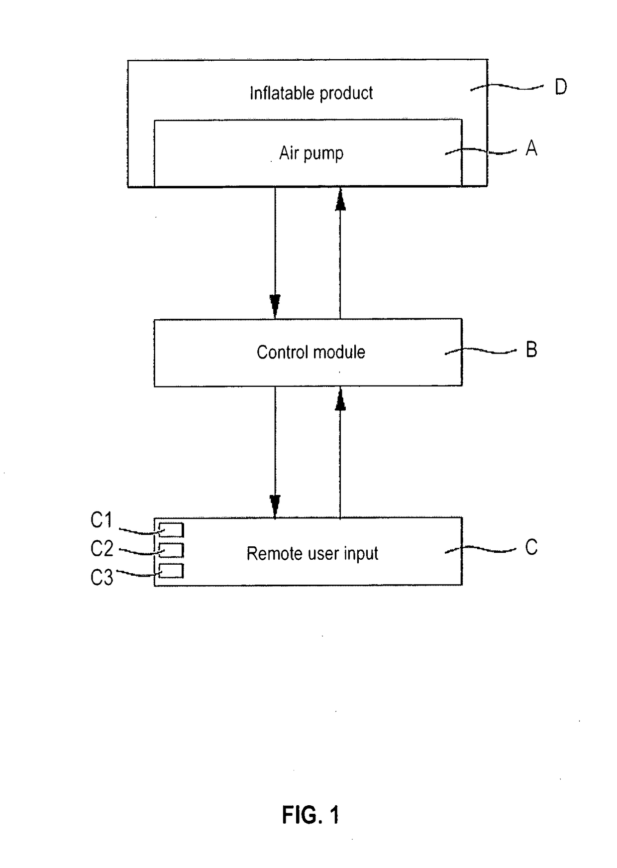
[0058]The housing 1 may be built into an inflatable chamber of the inflatable product D (FIG. 1). The housing 1 includes a cover panel 11 with a first opening 111 in fluid communication with the surrounding atmosphere. The housing 1 also includes a second opening or vent 12 in fluid communication with the inflatable product. The vent 12 is controlled by a one-way check valve 13 that is biased closed. In addition, the cover panel 11 includes an inflation switch or button 112, a deflation switch or button 113, an adjustment switch or button 114, and an indicator light 115 for displaying whether the system is operational, as described further below.
[0059]The air pump 2 includes a body 21, a blade 22, and a motor 23 that drives the blade 22. The body 21 defines an air inlet 211 and ...
second embodiment
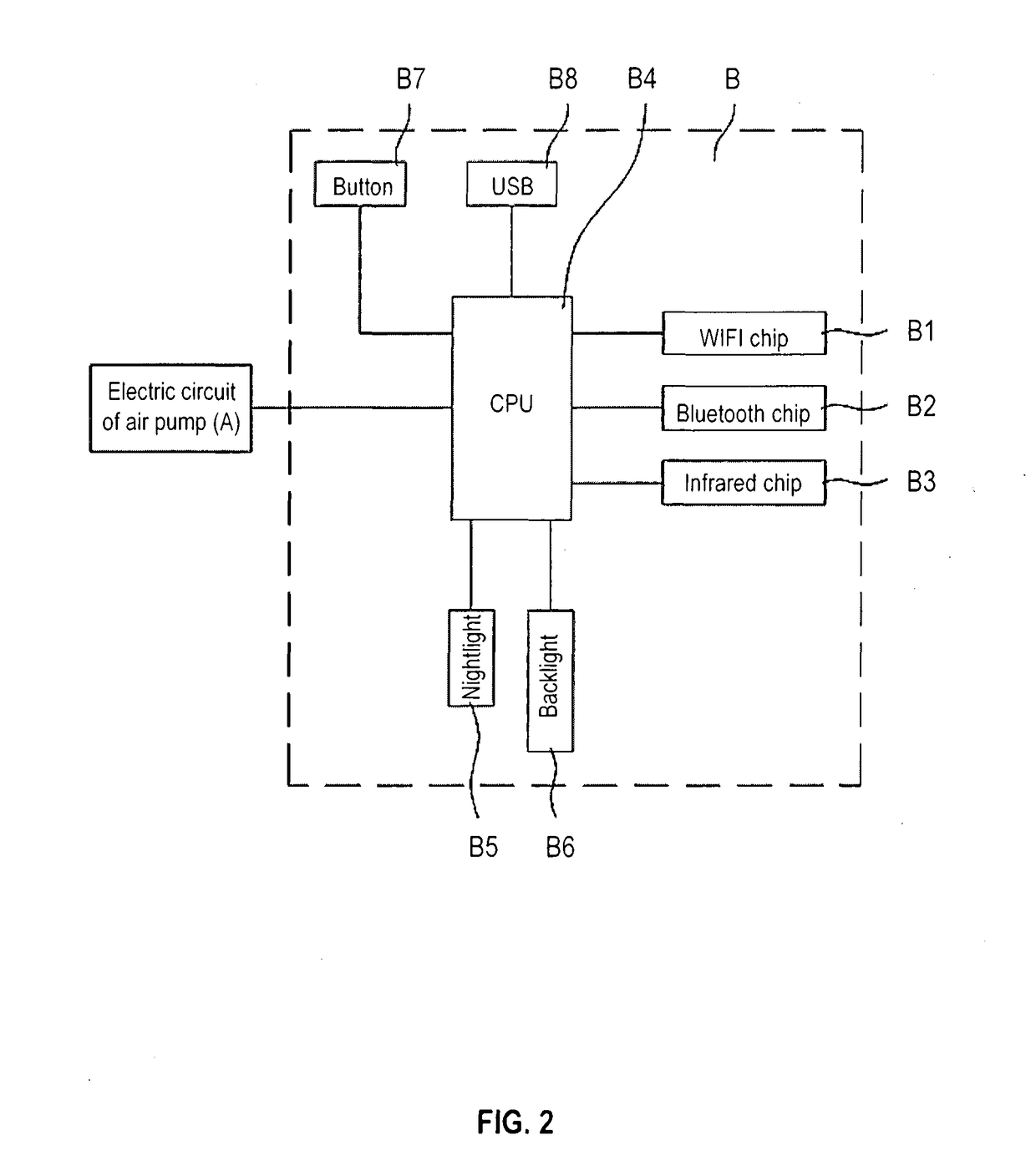
[0070]Referring next to FIGS. 9-15, the air pump assembly A′ is shown. The second air pump assembly A′ includes a seat or housing 1′, an air pump 2′ located within the housing 1′, and various other features in common with the first air pump assembly A, except as described below. Some of the elements discussed below may be considered part of the control module B (FIGS. 1 and 2).
[0071]The housing 1′ may be built into an inflatable chamber of the inflatable product D (FIG. 1). The housing 1′ includes an opening 11′ in fluid communication with the surrounding atmosphere. The housing 1′ also includes an opening or vent 12′ in fluid communication with the inflatable product. The vent 12′ is controlled by a one-way check valve 13′ that is biased closed. The housing 1′ also includes a timer 3′ and a current detector 4′. The housing 1′ may include a first chamber for the air pump 2′ and a separate chamber for the timer 3′ and the current detector 4′ such that the air pump 2′ is at least part...
third embodiment
[0082]Referring next to FIGS. 16-20, the air pump assembly A″ is shown. The third air pump assembly A″ includes a seat or housing 1″, an air pump 2″ located within the housing 1″, and various other features in common with the first and second air pump assemblies A, A′, except as described below. Some of the elements discussed below may be considered part of the control module B (FIGS. 1 and 2).
[0083]The housing 1″ may be built into an inflatable chamber of the inflatable product D (FIG. 1). The housing 1″ includes an opening 11′ in fluid communication with the surrounding atmosphere. The housing 1″ also includes an opening or vent 12″ in fluid communication with the inflatable product. The vent 12″ is controlled by a one-way check valve 13″ that is biased closed. The housing 1″ also includes a cover panel 10″ with an indicator light 101″ and a digital display 102″. The housing 1″ further includes a detection hole 17″ in fluid communication with the inflatable product, an electronic ...
PUM
 Abstract
Description
Claims
Application Information