
Light-emitting apparatus and display apparatus

Active Publication Date: 2018-11-29
CANON KK
View PDF0 Cites 17 Cited by
  • Summary
  • Abstract
  • Description
  • Claims
  • Application Information

AI Technical Summary

Benefits of technology

The present invention provides a light-emitting apparatus and a display apparatus which use a conversion member to control brightness and color of emitted light, while reducing color irregularities and improving image quality. The apparatus includes a light-source unit, a sheet member containing a conversion member, and an upper-surface member with an opening that connects to an outside space. The conversion member emits light of a different color based on the length of the light path inside the apparatus. This provides a more uniform and high-quality display image.

Problems solved by technology

However, when the local dimming control or the HDR control is performed using a conventional light-emitting apparatus including a conversion member, unintended color irregularities occur in light emitted from the light-emitting apparatus, a display image, or the like.

Method used


Image

  • Light-emitting apparatus and display apparatus
  • Light-emitting apparatus and display apparatus
  • Light-emitting apparatus and display apparatus

Examples


first embodiment

[0053]Hereinafter, a description will be given of a first embodiment of the present invention.

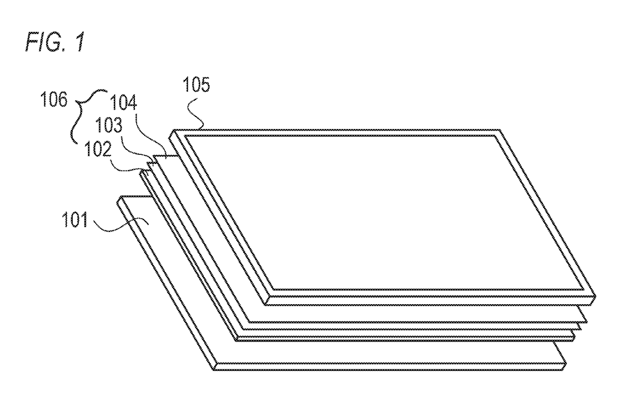
[0054]A light-emitting apparatus according to the embodiment may be used in a display apparatus including a display panel that displays an image by transmitting light emitted from the light-emitting apparatus on the basis of input image data. For example, the light-emitting apparatus according to the embodiment may be used as a backlight unit of a liquid-crystal display apparatus having a liquid-crystal panel as a display panel. The light-emitting device according to the embodiment may also be used in a micro electro mechanical system (MEMS) shutter display apparatus including a MEMS shutter instead of liquid-crystal elements.

[0055]The light-emitting apparatus according to the embodiment may also be used in a display apparatus such as an advertisement sign apparatus and a sign display apparatus. The light-emitting apparatus according to the embodiment may also be used as an illumination app...

second embodiment

[0110]Hereinafter, a description will be given of a second embodiment of the present invention. Note that in the second embodiment, points (configurations, processing, or the like) different from those of the first embodiment will be described in detail and the same points as those of the first embodiment will be omitted. The first embodiment describes an example in which the occurrence of unintended color irregularities may be reduced. The second embodiment will describe an example in which the brightness distribution of light emitted from a light-emitting apparatus may be improved, while the occurrence of unintended color irregularities may be reduced.

[0111]FIG. 15 is a perspective view showing a configuration example of a QD box 517 according to the second embodiment. A plurality of openings 116 are provided on the QD box 517. The number of the openings 116 provided on one QD box 517 is not particularly limited, but four openings 116 are provided on the one QD box 517 in the exam...

third embodiment

[0122]Hereinafter, a description will be given of a third embodiment of the present invention. Note that in the third embodiment, points (configurations, processing, or the like) different from those of the first and second embodiments will be described in detail and the same points as those of the first and second embodiments will be omitted.

[0123]The first and second embodiments describe an example in which the outer shape of a QD box in its surface parallel to a light-emitting surface is a substantially quadrilateral shape. The third embodiment will describe an example in which the outer shape of a QD box in its surface parallel to a light-emitting surface is a substantially hexagonal shape. The outer shape of the QD box in the surface parallel to the light-emitting surface may also be called the “shape of a part, which corresponds to the internal space of the QD box, of the light-emitting surface.”

[0124]FIG. 23 is a schematic view showing an example of the outer shape of QD boxe...


PUM


Abstract

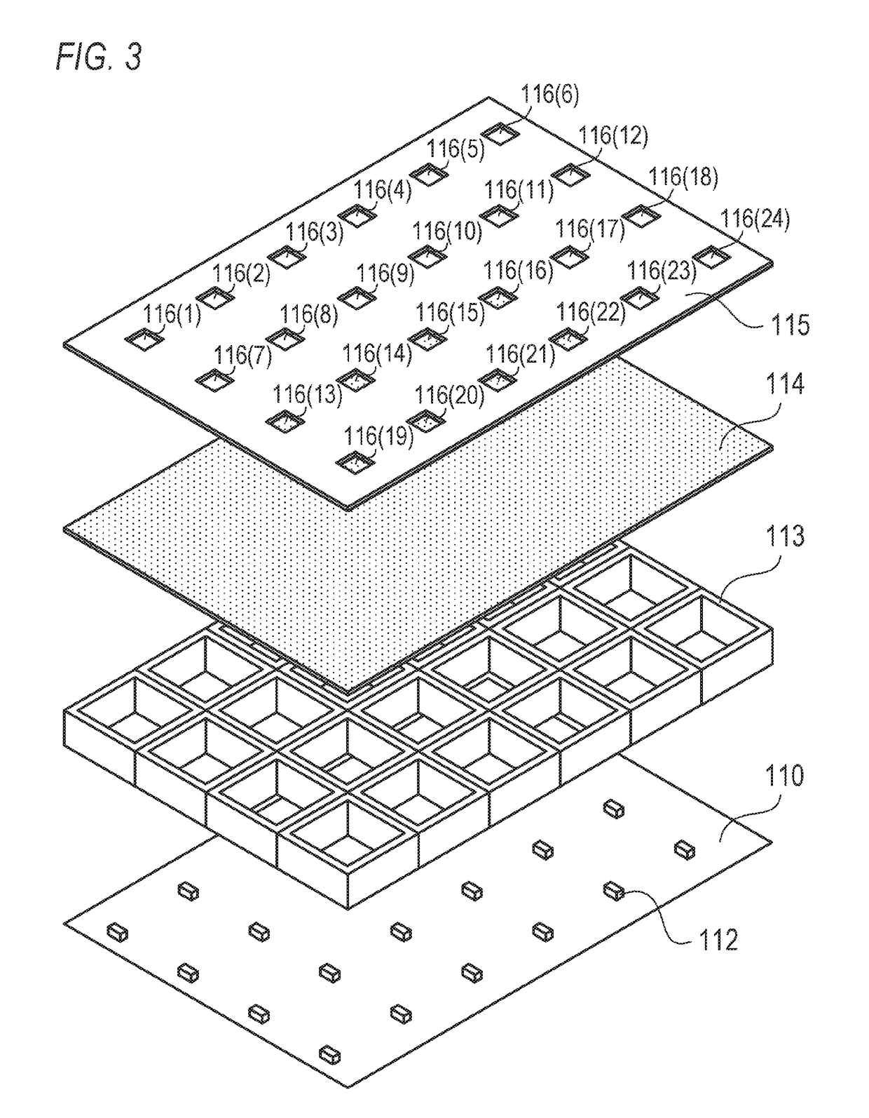
A light-emitting apparatus includes: a light-source unit configured to emit light of a first color; a sheet member containing a conversion member configured to emit light of the first color and light of a second color, according to incidence of the light emitted from the light-source unit; a bottom-surface member; a side-surface member; and an upper-surface member, wherein the sheet member emits the light of the second color by a light amount corresponding to a length of a path where the incident light of the first color passes through the sheet member, a space including the light-source unit and the conversion member is formed by the bottom-surface member, the side-surface member, and the upper-surface member, and a first opening connecting an inside and an outside of the space is provided at a position, on the upper-surface member, which does not face the light-source unit.

Description

BACKGROUND OF THE INVENTIONField of the Invention[0001]The present invention relates to a light-emitting apparatus and a display apparatus.Description of the Related Art[0002]Color image display apparatuses including a color liquid-crystal panel having a color filter and a light-emitting apparatus (backlight apparatus) irradiating white light onto the back surface of the color liquid-crystal panel have been known. Conventionally, fluorescent lamps such as cold cathode fluorescent lamps (CCFLs) have been mainly used as the light sources of light-emitting apparatuses. In recent years, however, light-emitting diodes (LEDs) excellent in power consumption, service life, color reproducibility, and environmental loads have been used as the light sources of light-emitting apparatuses.[0003]Light-emitting apparatuses (LED backlight apparatuses) including LEDs as light sources have been known. For example, a LED backlight apparatus disclosed in Japanese Patent Application Laid-open No. 2014-4...

Claims


Application Information

Patent Timeline
IPC IPC(8): G02F1/1335G02F1/017
CPCG02F1/133603G02F1/133621G02F1/133605G02F1/133606G02F1/017G02F2001/01791F21Y2105/10F21Y2115/10F21V9/30G02F1/133608G02F1/133601G02F1/133614G02F1/01791
Inventor KURITA, MASANAO
Owner CANON KK
Learn More