Operation method of copper smelting furnace

Active Publication Date: 2018-12-06
PAN PACIFIC COPPER CO LTD
View PDF5 Cites 0 Cited by
  • Summary
  • Abstract
  • Description
  • Claims
  • Application Information

AI Technical Summary

Benefits of technology

[0008]According to the present invention

Problems solved by technology

However, it was not possible to deal with degradation of an operation (degradation of a slag loss) caused by the shifting.
In a condition that it is not possible to change a mixing ratio of materials, there a

Method used


Image

  • Operation method of copper smelting furnace
  • Operation method of copper smelting furnace
  • Operation method of copper smelting furnace

Examples


embodiment

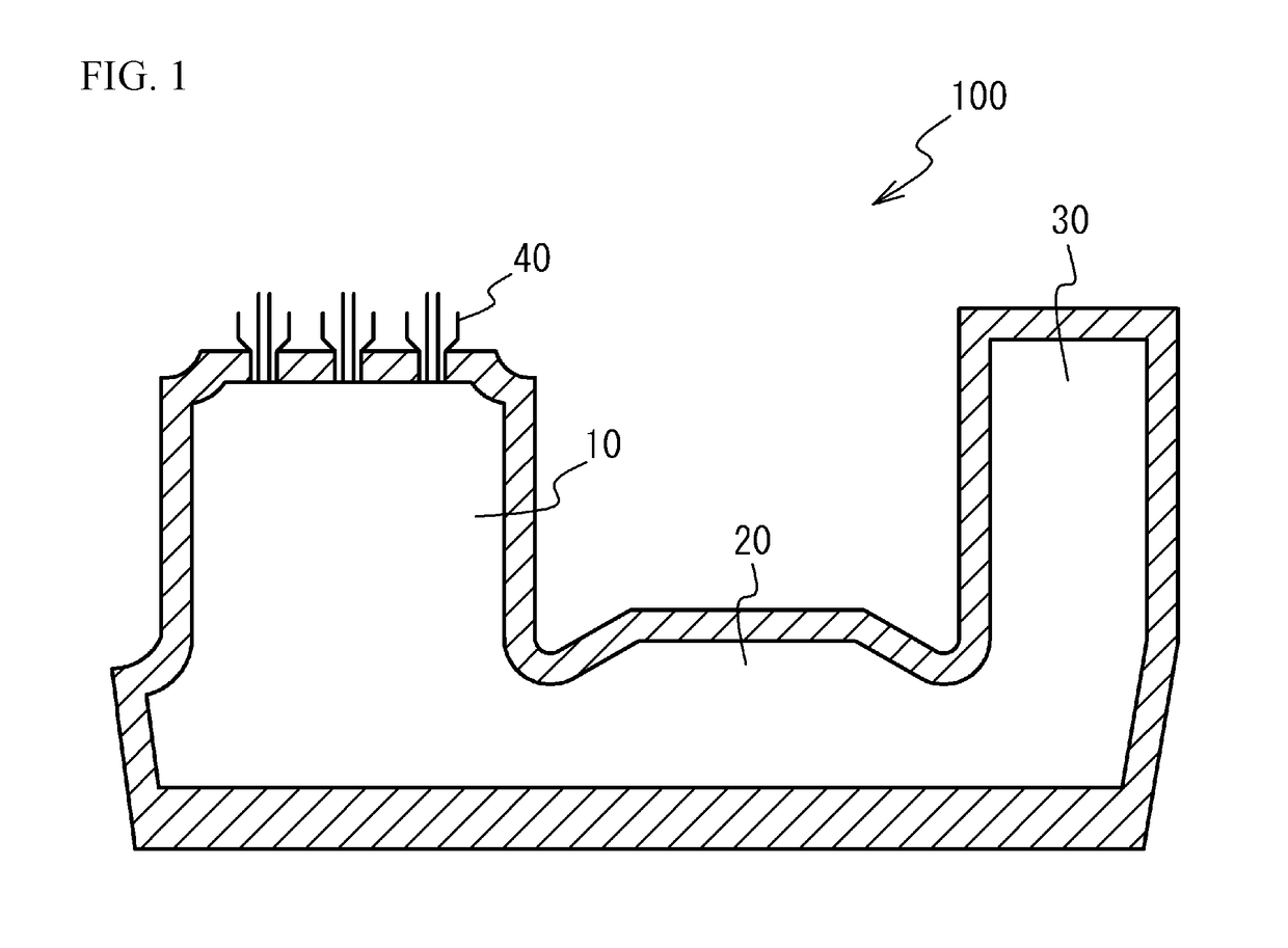
[0012]FIG. 1 illustrates a schematic view of a flash furnace 100 used in an embodiment of a copper-smelting method. As illustrated in FIG. 1, the flash furnace 100 has a structure in which a reaction shaft 10, a settler 20 and an uptake 30 are arranged in this order. A concentrate burner 40 is provided on an upper part of the reaction shaft 10.

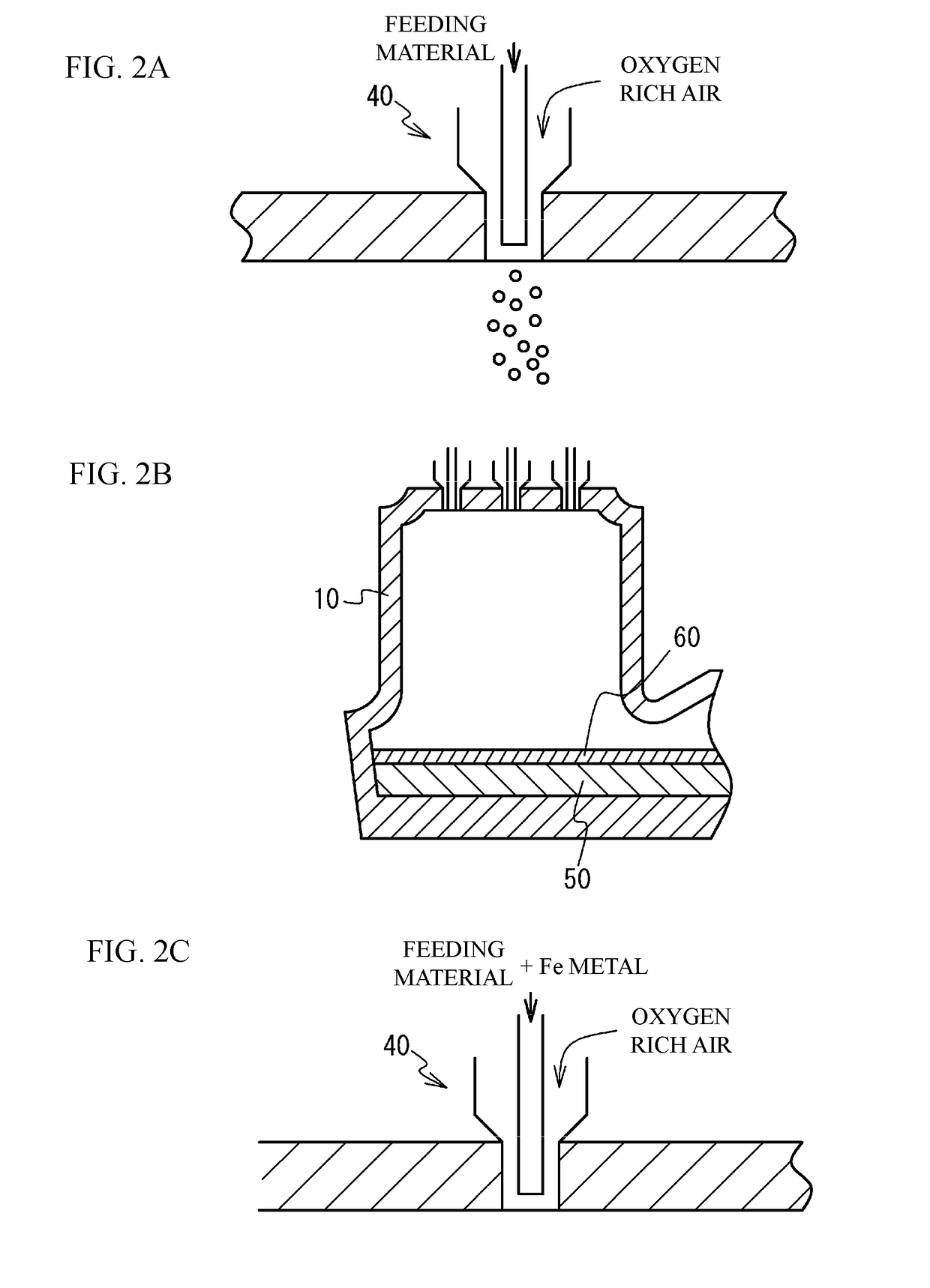
[0013]FIG. 2A and FIG. 2B illustrate a flowchart of a copper smelting using the flash furnace 100. As illustrated in FIG. 2A, reaction gas including oxygen is supplied into the reaction shaft 10 through the concentrate burner 40 together with a raw material for copper-smelting, a flux, a recycle raw material and so on (hereinafter, these solid materials are referred to as a feeding material). The raw material for copper-smelting is such as copper concentrate or the like. Thus, the raw material for copper-smelting causes an oxidation reaction on the basis of the following reaction formula (1) or the like. And, as illustrated in FIG. 2B, matte 5...

example

Example

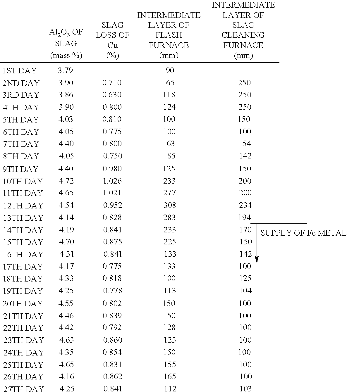
[0030]The copper smelting furnace was operated in accordance with the embodiment. Table 1 shows an operation condition and results. From a first day to 13th day, an average supply amount of the feeding material was 200 t / h, and the Fe metal source was not supplied. From 14th day, the average supply amount of the feeding material was 208 t / h. The average supply amount of the Fe metal source was 42 kg / h. The Fe metal source was supplied through the concentrate burner after mixing with the feeding material in advance. The Fe metal source included Fe metal of 55 mass % to 65 mass %. The supply amount of the oxygen rich air was 650 Nm3 / min to 690 Nm3 / min.

[0031]From the first day to the 13th day, when the Al2O3 concentration in the feeding material increases, the Al2O3 concentration in the slag exceeded 4.5 mass %. This resulted in the slag loss of 1% or more. This is because a high allowable concentration of Al2O3 was not achieved with respect to the slag and Fe3O4 was stabilized ...


PUM

PropertyMeasurementUnit
Percent by massaaaaaaaaaa

Abstract

An operation method of a copper-smelting furnace is characterized by including supplying an Fe metal source into a copper-smelting furnace together with a feeding material including copper concentrate and a flux, the copper concentrate including Al, the Fe metal source including an Fe metal of 40 mass % to 100 mass %.

Description

TECHNICAL FIELD[0001]The present invention relates to an operation method of a copper smelting furnace.BACKGROUND ART[0002]Recently, a material to be treated in a copper smelting tends to be shifted from a material that is mainly composed of copper concentrate to a material of which a high profit material ratio is increased. However, it was not possible to deal with degradation of an operation (degradation of a slag loss) caused by the shifting. When a high margin material is treated, a generation amount of a hardly meltable substance of which a main component is magnetite (Fe3O4) increases in a furnace. However, a mechanism is not specified. It is possible only to deal with degradation of a furnace condition after the condition is degraded. In a condition that it is not possible to change a mixing ratio of materials, there are no other effective solving means. The degradation of the operation is forced for a long time. Therefore, a profit is greatly degraded.[0003]There is disclose...

Claims


Application Information

Patent Timeline
IPC IPC(8): C22B15/04C22B5/02C22B15/00
CPCC22B15/0036C22B5/02C22B15/0052C22B5/04Y02P10/20C22B15/0095
Inventor MOTOMURA, TATSUYASOMA, YUKI
Owner PAN PACIFIC COPPER CO LTD
Why Eureka
Try Eureka