
Control system for work vehicle, method for setting trajectory of work implement, and work vehicle

a control system and work implement technology, applied in vehicle position/course/altitude control, process and machine control, instruments, etc., can solve problems such as inefficiency, work implements cannot be operated according to target profiles, work vehicles may deviate from intended paths, etc., to achieve work efficiency and good finish quality

Active Publication Date: 2018-12-13
KOMATSU LTD
View PDF7 Cites 8 Cited by
  • Summary
  • Abstract
  • Description
  • Claims
  • Application Information

AI Technical Summary

Benefits of technology

The patent improves the efficiency and quality of work done by a work vehicle by allowing it to be controlled automatically.

Problems solved by technology

With this conventional system, however, the work implement cannot necessarily be operated according to the target profile.
For instance, the work vehicle may deviate from the intended path due to the properties of the soil, the gradient of the work site, and other such factors.
In that case, work according to the target profile on route that differs from the planned route may not be efficient.

Method used


Image

  • Control system for work vehicle, method for setting trajectory of work implement, and work vehicle
  • Control system for work vehicle, method for setting trajectory of work implement, and work vehicle
  • Control system for work vehicle, method for setting trajectory of work implement, and work vehicle

Examples


Embodiment Construction

)

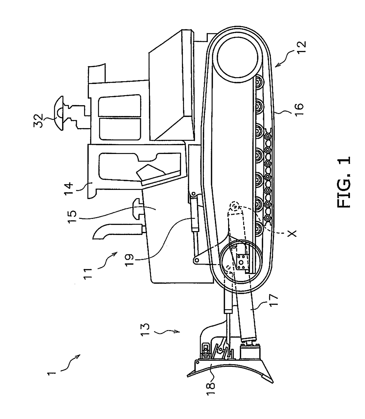
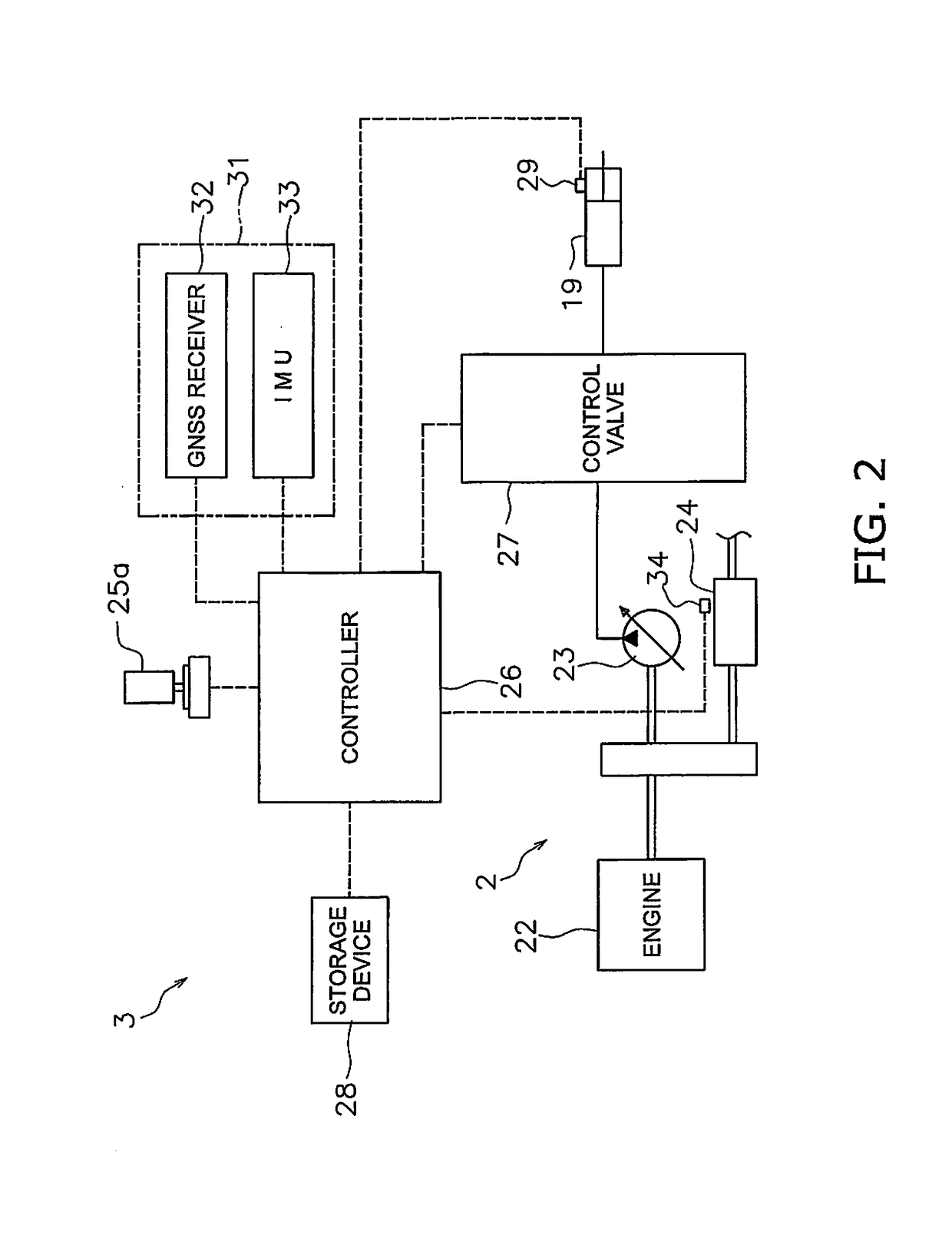
[0024]The work vehicle pertaining to an embodiment will now be described through reference to the drawings. FIG. 1 is a side view of the work vehicle 1 according to an embodiment. The work vehicle 1 in this embodiment is a bulldozer. The work vehicle 1 includes a vehicle body 11, a drive unit 12, and a work implement 13.

[0025]The vehicle body 11 has a cab 14 and an engine compartment 15. A driver's seat (not shown) is disposed in the cab 14. The engine compartment 15 is disposed in front of the cab 14. The drive unit 12 is attached to the lower portion of the vehicle body 11. The drive unit 12 has a pair of right and left crawler belts 16. Only the left crawler belt 16 is shown in FIG. 1. Rotation of the crawler belts 16 propels the work vehicle 1. The travel of the work vehicle 1 may be either autonomous travel, semi-autonomous travel, or travel under operation by the operator.

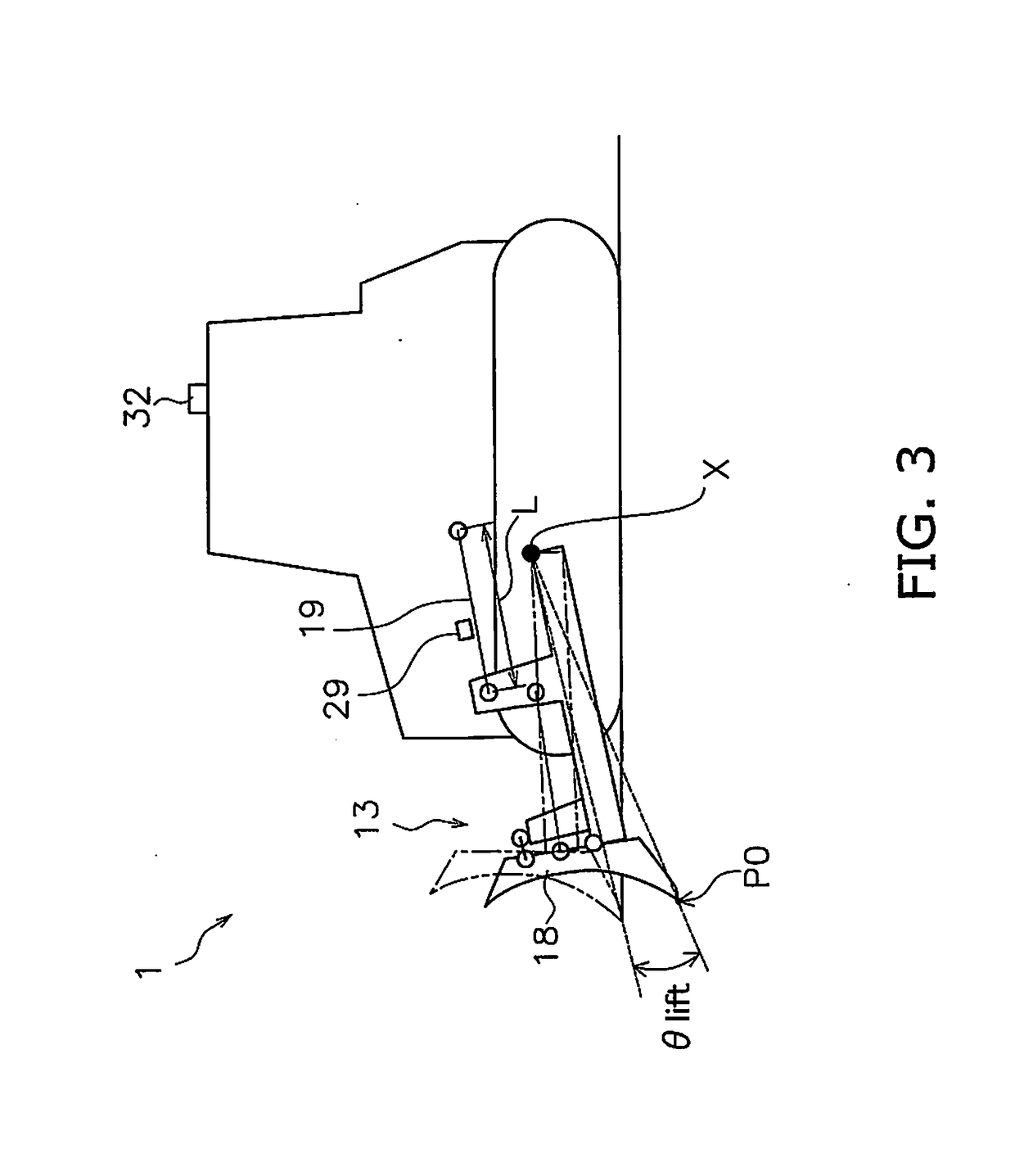
[0026]The work implement 13 is attached to the vehicle body 11. The work implement 13 has a lift frame 17...


PUM


Abstract

A control system for a work vehicle includes a controller. The controller acquires the travel direction of the work vehicle. The controller acquires current terrain data indicating a current terrain existing in the travel direction of the work vehicle. The controller decides a target profile of a work site based on the current terrain data. The controller generates a command signal to operate a work implement according to the target profile. The controller updates the travel direction of the work vehicle. The controller updates the target profile based on the updated travel direction.

Description

CROSS-REFERENCE TO RELATED APPLICATIONS[0001]This application is a U.S. National stage application of International Application No. PCT / JP2017 / 013732, filed on Mar. 31, 2017.BACKGROUNDField of the Invention[0002]The present invention relates to a control system for a work vehicle, a method for setting the trajectory of a work implement, and a work vehicle.Description of the Related Art[0003]A system for a bulldozer, a grader, or another such work vehicle has been proposed in the past in which, in order to carry out work more efficiently, a target profile by which a work implement is to operate at the work site is preset from the terrain at the work site, and the work implement is operated according to this target profile.SUMMARY[0004]With the above-mentioned conventional system, even an inexperienced operator can perform work efficiently. With this conventional system, however, the work implement cannot necessarily be operated according to the target profile. For instance, the work ...

Claims


Application Information

Patent Timeline
Patent Type & Authority Applications(United States)
IPC IPC(8): E02F9/26E02F3/84G05D1/02
CPCE02F9/262E02F3/841G05D1/0212G05D1/0278G05D2201/0202E02F3/844G05D1/0274E02F9/2045B60W30/10
Inventor HASHIMOTO, KAZUHIRO
Owner KOMATSU LTD
Learn More