
Pipe union assembly

a technology of pipe union and assembly, which is applied in the direction of screw threaded joints, couplings, manufacturing tools, etc., can solve the problems of high cost, high torque, unsafe practice, etc., and achieve the effect of simple, rugged and easy to install

Active Publication Date: 2018-12-13
PREMIUM OILFIELD TECH LLC
View PDF9 Cites 8 Cited by
  • Summary
  • Abstract
  • Description
  • Claims
  • Application Information

AI Technical Summary

Benefits of technology

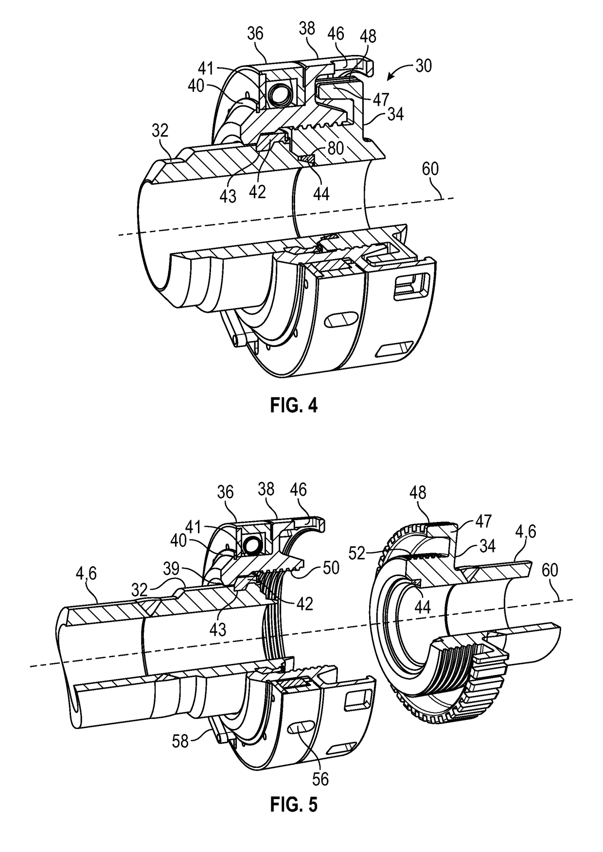
The present invention is a pipe union that uses a locknut and a torque ring to tighten the union without needing a hammer. The union can also be tightened by rotating the torque openings relative to the torque slots using mechanical advantage. The design also includes a ratcheting mechanism to engage the two parts of the union before final tightening. The pipe union creates a seal using an elastomeric or metal seal and angles on load shoulders to create preloads to seal the components.

Problems solved by technology

Not only is the practice unsafe, there is little ability to determine that the required torque has been reached.
The disadvantages are high cost and the use of four bolts requiring a high torque.
Assembly and disassembly is still time consuming, although less so than a flanged connection.

Method used


Image

  • Pipe union assembly
  • Pipe union assembly
  • Pipe union assembly

Examples


Embodiment Construction

[0036]The Figures described above and the written description of specific structures and functions below are not presented to limit the scope of what Applicant has invented or the scope of the appended claims. Rather, the Figures and written description are provided to teach any person skilled in the art to make and use the inventions for which patent protection is sought. Those skilled in the art will appreciate that not all features of a commercial embodiment of the inventions are described or shown for the sake of clarity and understanding. Persons of skill in this art will also appreciate that the development of an actual commercial embodiment incorporating aspects of the present disclosure will require numerous implementation-specific decisions to achieve the developer's ultimate goal for the commercial embodiment. Such implementation-specific decisions may include, and likely are not limited to, compliance with system-related, business-related, government-related, and other co...


PUM


Abstract

The present invention provides a pipe union that uses mechanical advantage from leverage between a locknut with circumferential torque openings coupled to a tubular first portion and a torque ring with torque slots coupled to a tubular second portion to tighten the union. The tightening can occur without the need of a hammer impact on lugs. Initial tightening can at least partially align longitudinally the radial holes with the radial slots. Final tightening can occur by rotating the torque openings relative to the torque slots using mechanical advantage. Optionally, the pipe union can provide for a ratcheting mechanism to turn the locknut on the tubular first portion to engage the tubular second portion and exert a preliminary torque on the union. The pipe union design also provides a self-energizing elastomeric seal or metal seal. Angles on load shoulders can assist in creating preloads on the union to seal the components.

Description

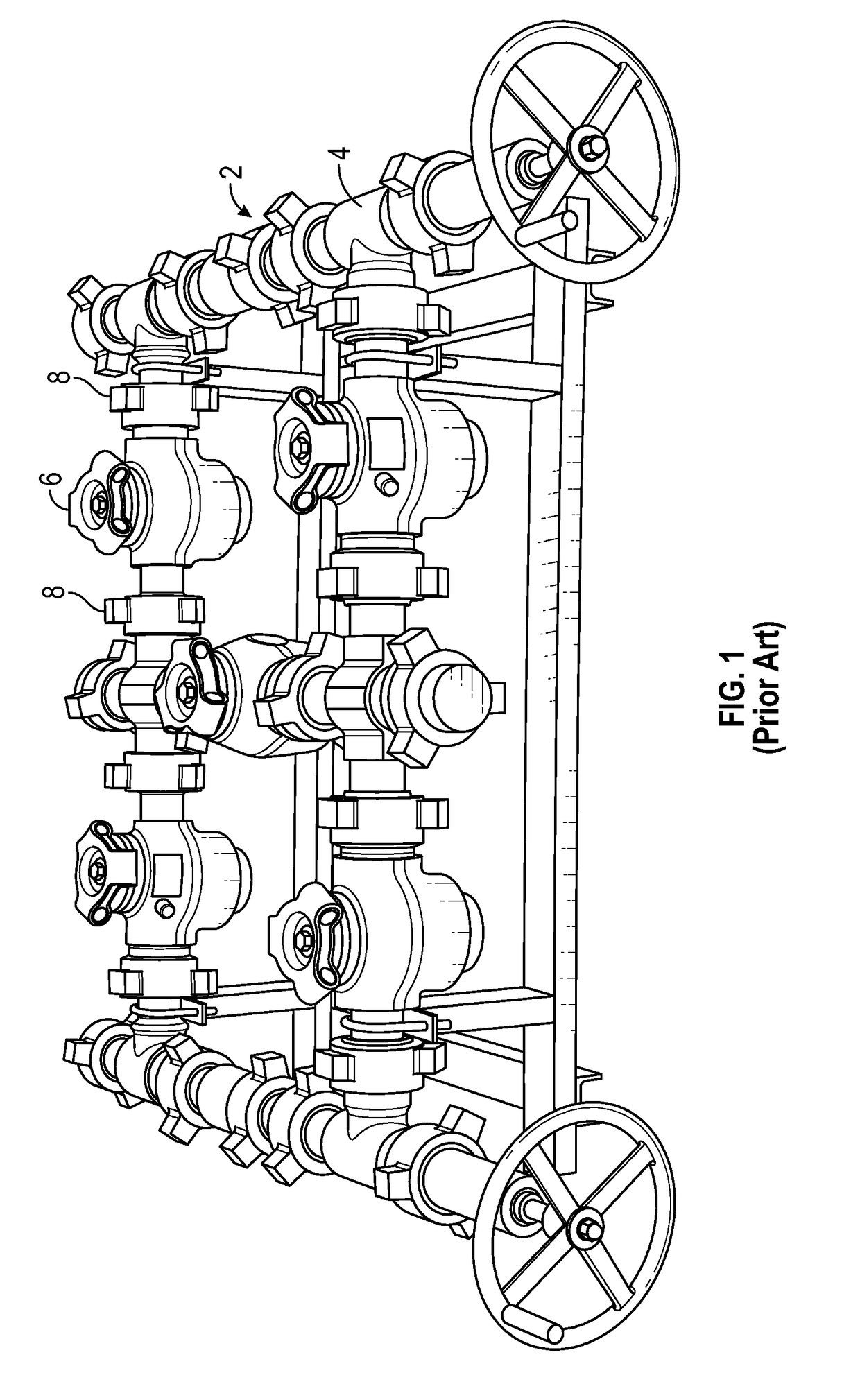
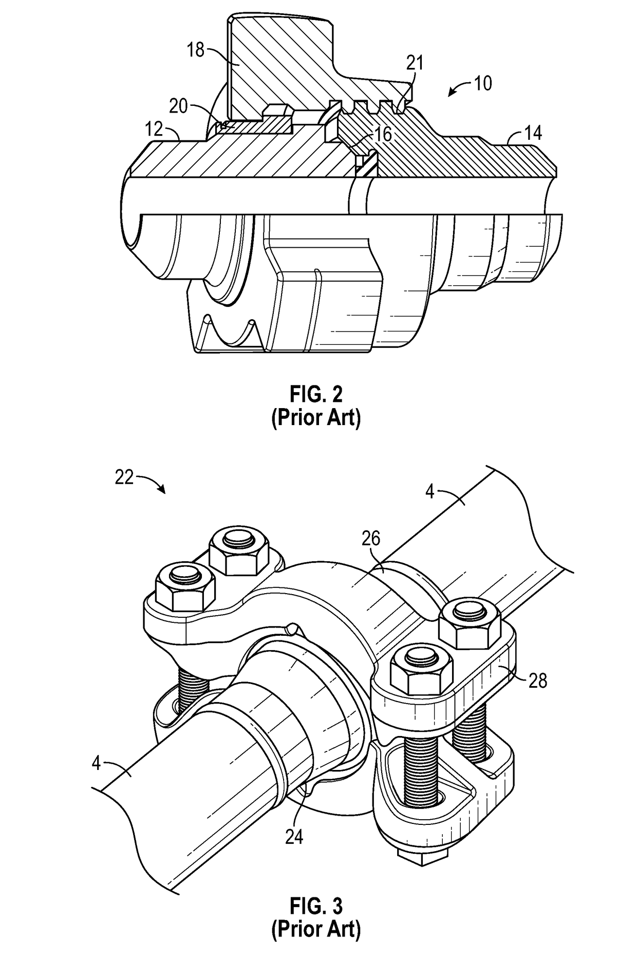
CROSS REFERENCE TO RELATED APPLICATIONS[0001]This application claims benefit of U.S. Provisional Application Ser. No. 62 / 518,839, entitled “Hammerless Pipe Union”, filed on Jun. 13, 2017 and is incorporated herein by reference.STATEMENT REGARDING FEDERALLY SPONSORED RESEARCH OR DEVELOPMENT[0002]Not applicable.REFERENCE TO APPENDIX[0003]Not applicable.BACKGROUND OF THE INVENTIONField of the Invention[0004]The disclosure relates generally to equipment used to connect pipes. More specifically, the disclosure relates to a coupling (union) that can use mechanical advantage to input torque on the union to tighten the connection.Description of the Related Art[0005]Conventional pipe couplings, such as unions, are used throughout most industries for connecting pipe, including tubing and other conduits. FIG. 1 is a typical known layout of a piping system with unions and other piping components. The piping system 2, such as a manifold, can include piping 4 coupled through a plurality of unions...

Claims


Application Information

Patent Timeline
IPC IPC(8): F16L15/08B25B13/46B25B13/50F16D41/07F16L21/02
CPCF16L15/08B25B13/46B25B13/50F16D41/07F16L21/02F16L2201/00B25B13/5091F16L19/0212F16L19/025F16L2201/20F16D41/08
Inventor JAHNKE, DOUGLAS
Owner PREMIUM OILFIELD TECH LLC
Learn More