Method for automatically calibrating a camshaft sensor for a motor vehicle engine and associated sensor

a technology of camshaft sensor and engine, which is applied in the direction of automatic recalibration, conversion of sensor output, instruments, etc., can solve the problems of mass-produced and often exhibit imperfect geometry, sensor is sensitive to the positioning of the target on the camshaft and the geometry of the target, and the air gap between the sensor and the target is often affected, so as to achieve the effect of reducing the disadvantag

Active Publication Date: 2018-12-13
CONTINENTAL AUTOMOTIVE FRANCE +1
View PDF0 Cites 13 Cited by
  • Summary
  • Abstract
  • Description
  • Claims
  • Application Information

AI Technical Summary

Benefits of technology

The present invention proposes a method to automatically calibrate a camshaft sensor. This calibration method helps to avoid false detections and corrects any out-of-roundness of a target and airgap defect between the sensor and the target. The method involves decreasing the switching threshold after the magnetic field exceeds a certain threshold. This invention makes it easier to accurately detect and measure the position of the camshaft.

Problems solved by technology

Now, the sensors have the disadvantage of being sensitive to the positioning of the target on the camshaft and to the geometry of this target.
For cost reasons, the targets, which are simple pieces of metal equipped with teeth of predetermined dimensions and predetermined spacings, are mass-produced and often exhibit imperfect geometry.
There are also defects with the air gap between the sensor and the target, these defects varying with time and being sensitive to temperature.
These variations in magnetic field may impair the measurements taken (impair the precision of the position of the electrical edges in relation to the mechanical edges) or may even fail to be interpreted by the sensor (non-detection of a tooth, the magnetic field being below the switching threshold).
The signal delivered by the camshaft sensor is then erroneous and correct determination of the position of each cylinder in the engine cycle is corrupted or even impossible.
However, this method of automatically calibrating a camshaft sensor of the prior art has one major disadvantage.

Method used


Image

  • Method for automatically calibrating a camshaft sensor for a motor vehicle engine and associated sensor
  • Method for automatically calibrating a camshaft sensor for a motor vehicle engine and associated sensor
  • Method for automatically calibrating a camshaft sensor for a motor vehicle engine and associated sensor

Examples


Embodiment Construction

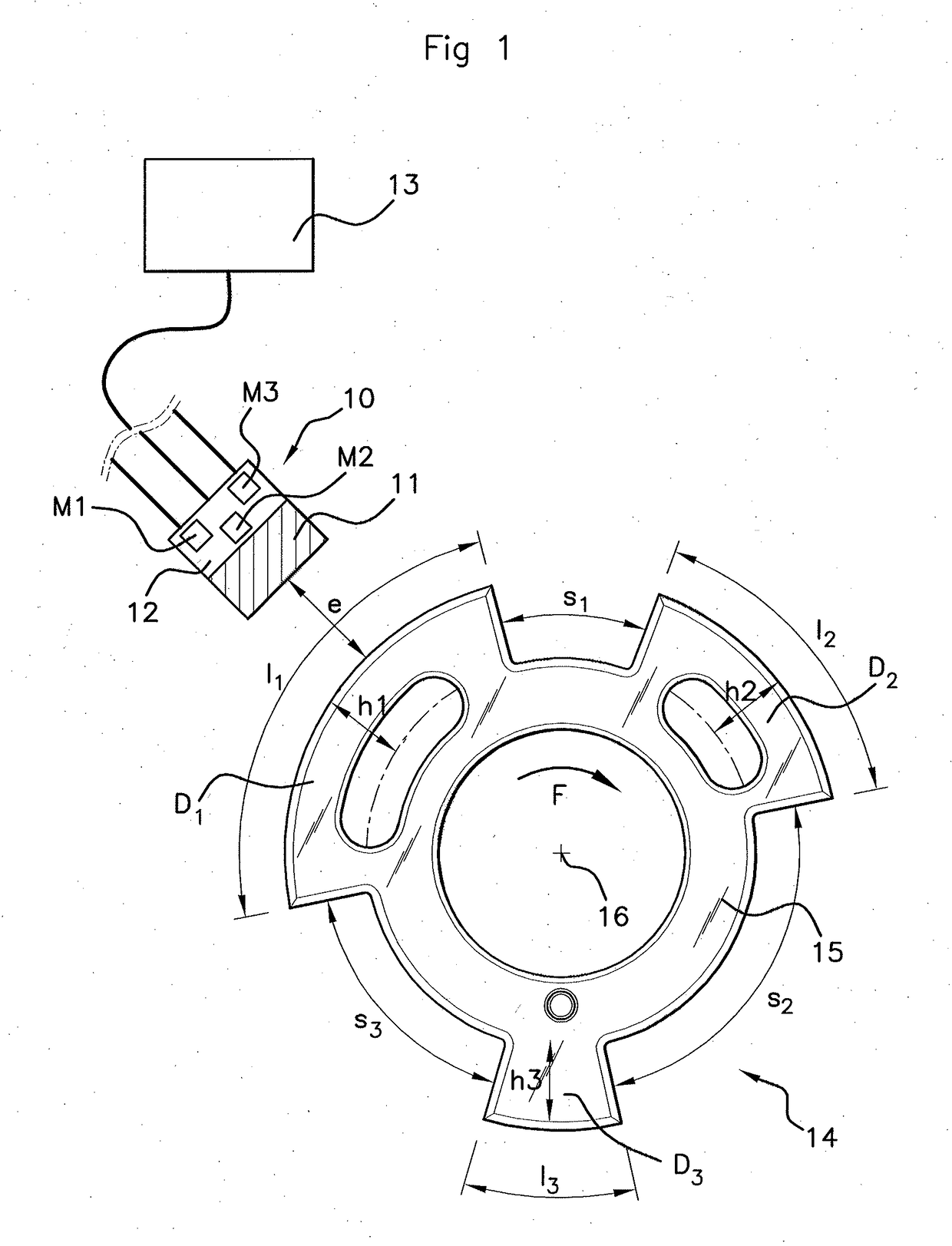
[0043]According to the embodiment described and depicted in FIGS. 1 to 3, a camshaft sensor 10 comprises a ferromagnetic element 11 and a magnetic field detection means 12 (for example a Hall-effect cell). This sensor 10 delivers a digital signal to a central processor 13.

[0044]A target 14 associated with this sensor 10 takes the form of a metal disk 15 firmly attached to a camshaft 16. This target bears, on its periphery, a plurality of teeth D1, D2, D3 (3 in the example depicted) of different heights h1, h2, h3 and of variable lengths l1 to l3 and variable spacings (troughs) s1 to s3. These variable lengths and variable spacings in the way known per se constitute a coding.

[0045]The way in which a sensor 10 plus target 14 assembly works is described hereinafter.

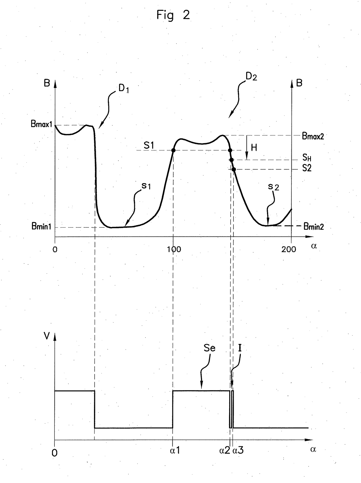
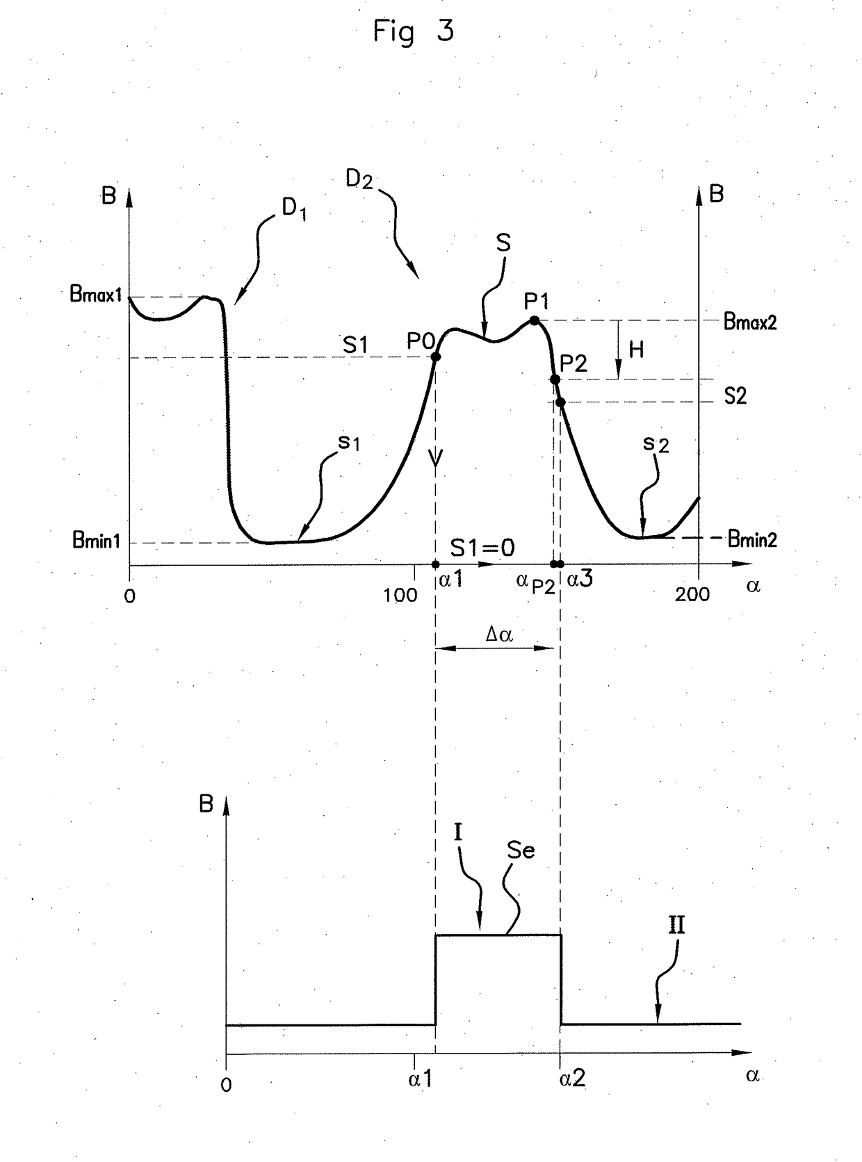
[0046]When the target 14 is rotationally driven (arrow F FIG. 1) by the camshaft 16, the sensor 10 perceives a series of variations in values of the magnetic field B indicative of the length l of the teeth D1, D2, D3 moving ...


PUM


Abstract

A method for automatically calibrating an engine camshaft sensor, the sensor measuring variations in magnetic field value and delivering an electrical signal having a high state after the passage of the values of the magnetic field above the switching threshold on a rising edge and a low state after the passage of the values of the magnetic field below the switching threshold on a falling edge. After the passage of the values of the magnetic field above the switching threshold and measuring a new maximum value, the electrical signal remains in a high state as long as the magnetic field values are higher than a hysteresis threshold, which is dependent on the amplitude of the magnetic field calculated with the measured new maximum value; after the passage of the values of the magnetic field below the hysteresis threshold, a new switching threshold is calculated according to the new maximum value.

Description

CROSS REFERENCE TO RELATED APPLICATIONS[0001]This application is the U.S. National Phase Application of PCT International Application No. PCT / EP2016 / 001931, filed Nov. 18, 2016, which claims priority to French Patent Application No. 1561387, filed Nov. 25, 2015, the contents of such applications being incorporated by reference herein.FIELD OF THE INVENTION[0002]The present invention relates to a method for automatically calibrating a camshaft sensor for a motor vehicle. More particularly, it is a matter of determining automatically the “out-of-roundness” of a toothed wheel (also referred to as target) mounted on the end of a motor vehicle engine camshaft.BACKGROUND OF THE INVENTION[0003]Camshaft sensors are used in a motor vehicle to determine the position of the various cylinders in the engine combustion cycle, namely to determine whether each cylinder is in the admission phase, the compression phase, the combustion phase or the exhaust phase. These sensors generally comprise a mag...

Claims


Application Information

Patent Timeline
IPC IPC(8): G01D5/244G01D5/14G01D18/00G01M15/06
CPCG01D5/2448G01D5/145G01D18/002G01M15/06G01D5/24471
Inventor MIRASSOU, DAVID
Owner CONTINENTAL AUTOMOTIVE FRANCE
Why Eureka
Try Eureka