Communication apparatus and communication method

a communication apparatus and communication method technology, applied in the field of communication apparatus and communication methods, can solve problems such as inter-user interference, and achieve the effect of improving the frequency efficiency of the communication system and improving the reception quality of signals

Inactive Publication Date: 2018-12-13
SHARP KK
View PDF4 Cites 15 Cited by
  • Summary
  • Abstract
  • Description
  • Claims
  • Application Information

AI Technical Summary

Benefits of technology

[0022]According to an aspect of the present invention, a transmission station and a reception station can simultaneously direct main beams the number of which exceeds the number N of RF systems provided to themselves to the reception station and transmission station, respectively, which improves reception quality of the signals, and thus, improves frequency efficiency of the communication system.

Problems solved by technology

Inter-user interference is caused because multiple terminal apparatuses are non-orthogonally multiplexed to perform transmission by a base station apparatus.

Method used


Image

  • Communication apparatus and communication method
  • Communication apparatus and communication method
  • Communication apparatus and communication method

Examples


first embodiment

1. First Embodiment

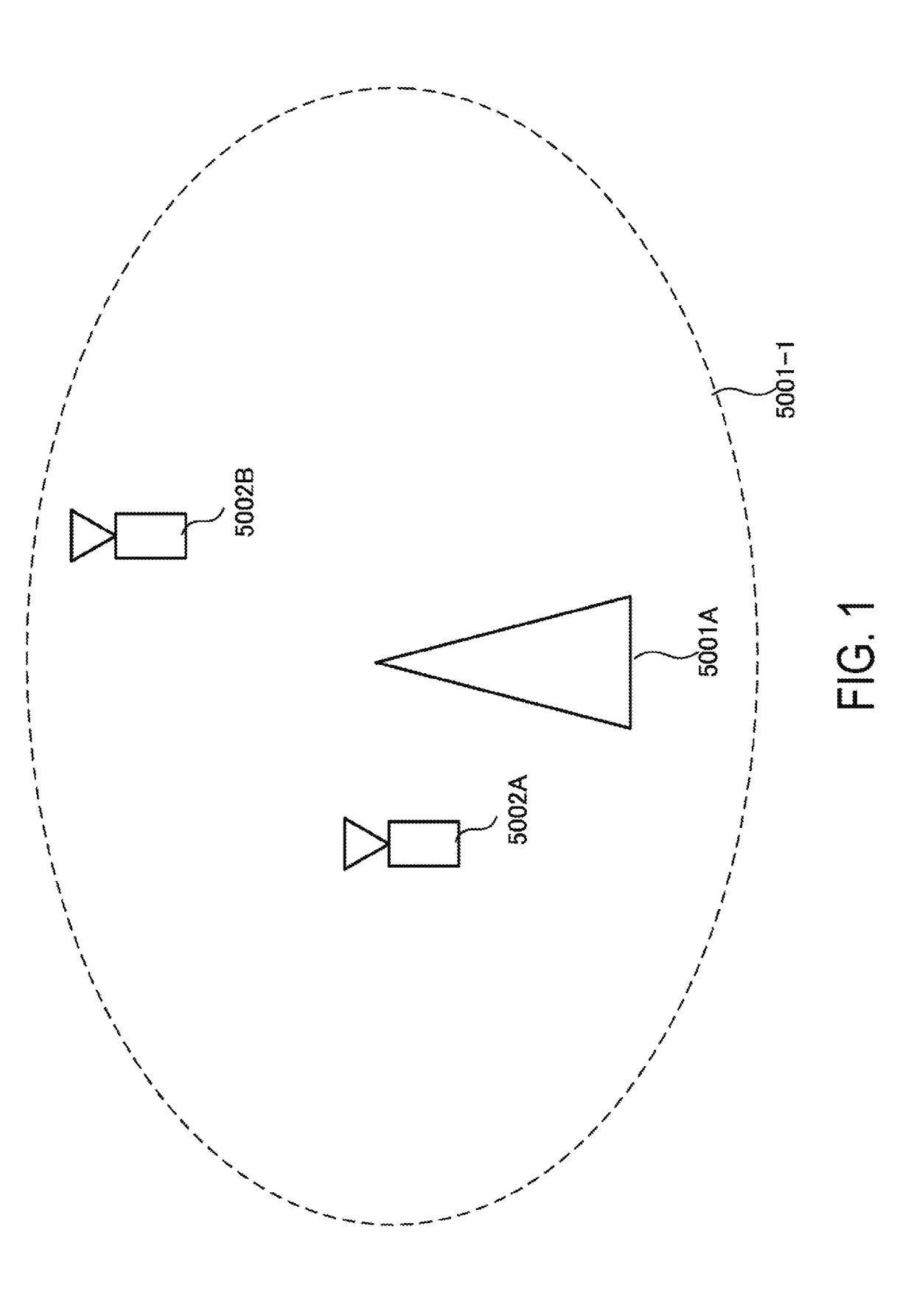
[0031]FIG. 1 is a diagram illustrating an example of a communication system according to the present embodiment. As illustrated in FIG. 1, the communication system according to the present embodiment includes a base station apparatus 5001A and terminal apparatuses 5002A and 5002B. A coverage 5001-1 is a range (a communication area) in which the base station apparatus 5001A can connect to the terminal apparatuses. The terminal apparatuses 5002A and 5002B are also collectively referred to as terminal apparatuses 5002.

[0032]With respect to FIG. 1, the following uplink physical channels are used for uplink radio communication from the terminal apparatus 5002A to the base station apparatus 5001A. The uplink physical channels are used for transmission of information output from higher layers.[0033]Physical Uplink Control Channel (PUCCH)[0034]Physical Uplink Shared Channel (PUSCH)[0035]Physical Random Access Channel (PRACH)

[0036]The PUCCH is used for transmission of Upli...

modification example 1

1.2. Modification Example 1

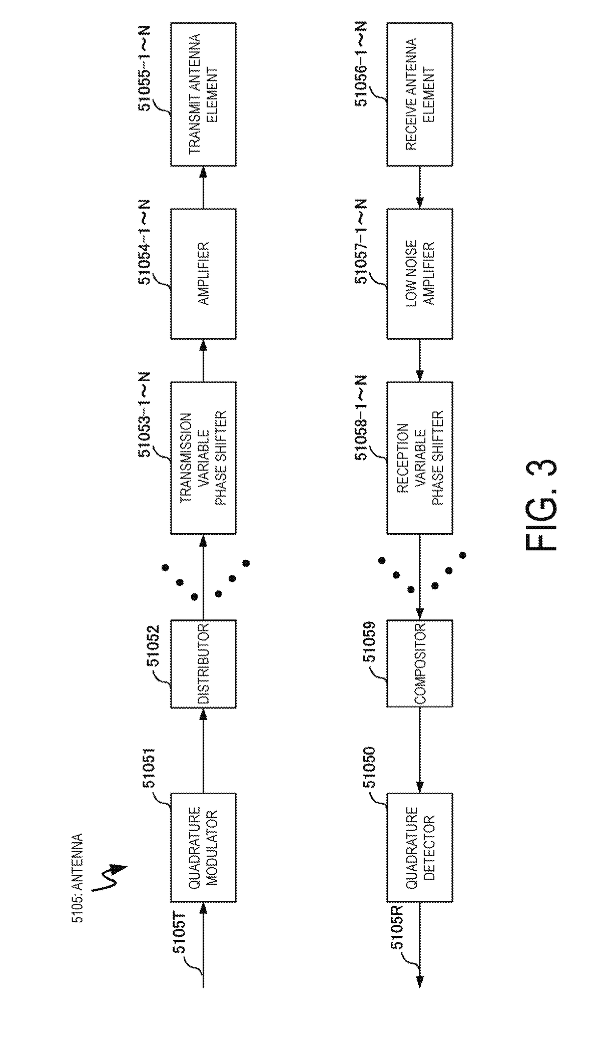
[0170]The present modification example deals with a case that the configuration of the antenna 5105 is different.

[0171]In the present modification example, the configuration of the antenna 5105 is not limited to a phased array antenna configuration. For example, a configuration of a surface scattering antenna as disclosed in Japanese patent application publication No. 2013-539949 may be included in the present modification example. Further, the surface scattering antenna may include metamaterial elements.

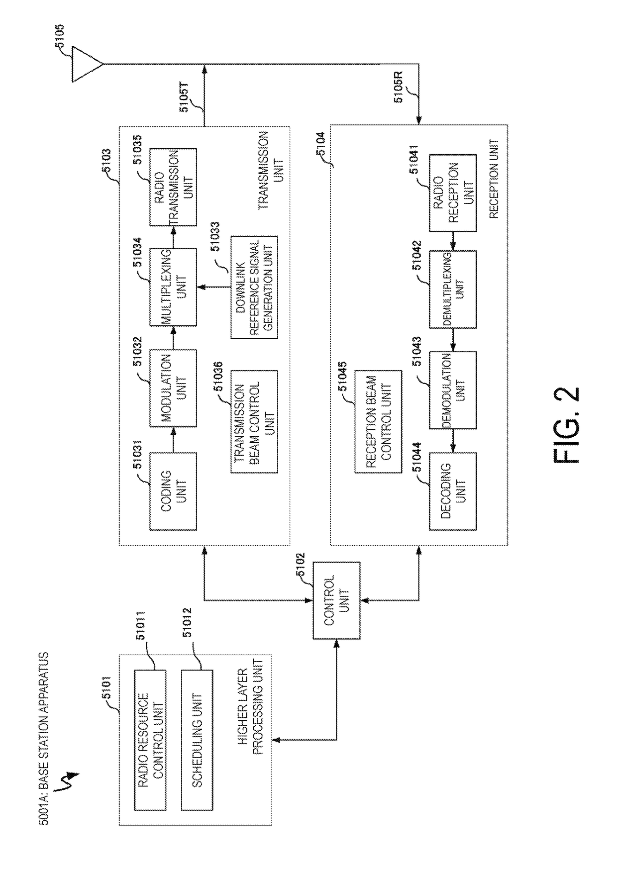
[0172]The surface scattering antenna includes adjustable scattering elements having electromagnetic properties that are adjustable in response to external inputs. In the present modification example, the transmission beam control unit 51036 and the reception beam control unit 51045 have a function to generate external input information adjusting the scattering elements.

[0173]The surface scattering antenna can form a specific antenna directivity pattern by ...

second embodiment

2. Second Embodiment

[0177]The base station apparatus 5001A according to the present embodiment communicates with the terminal apparatus 5002A. The configurations of the base station apparatus 5001A and terminal apparatus 5002A according to the present embodiment are the same as those in the first embodiment. Hereinafter, a method according to the present embodiment is described focusing on points different from the first embodiment.

[0178]The downlink signal transmitted from the base station apparatus 5001A arrives the terminal apparatus 5002A via not only a direct wave (direct path, direct arrival path) but also a reflected wave (reflection path, delay path). To he more specific, there are multiple paths between the base station apparatus 5001A and the terminal apparatus 5002A,

[0179]The base station apparatus 5001A according to the present embodiment can direct multiple main beams to the terminal apparatus 5002A. Moreover, the base station apparatus 5001A can direct the multiple mai...


PUM


Abstract

To provide a communication apparatus and a communication method capable of simultaneously directing main beams to reception stations and transmission stations the numbers of which exceed the number N of RF systems provided to the communication apparatus itself. The communication apparatus according to the present invention includes a transmission unit configured to generate non-orthogonal multiplexed signals including downlink signals addressed to multiple terminal apparatuses, an antenna capable of forming an antenna directivity pattern including multiple main beams, and a transmission beam control unit configured to generate a signal controlling the antenna directivity pattern, wherein the non-orthogonal multiplexed signals are simultaneously transmitted by use of the multiple main beams, and the number of main beams included in the antenna directivity pattern is more than the number of RF systems of the antenna.

Description

TECHNICAL FIELD[0001]The present invention relates to a communication apparatus and a communication method.BACKGROUND ART[0002]In a communication system such as Long Term Evolution (LTE) or LTE-Advanced (LTE-A) standardized by the Third Generation Partnership Project (3GPP), the communication area can be widened by taking a cellular configuration in which areas covered by base station apparatuses (base stations, transmission stations, transmission points, downlink transmission devices, uplink reception devices, a group of transmit antennas, a group of transmit antenna ports, component carriers, eNodeB, access points, AP) or transmission stations equivalent to the base station apparatuses are arranged in the form of multiple cells (Cells) being linked together. In such a cellular configuration, frequency efficiency can be improved by using the same frequency among neighboring cells or sectors.[0003]In recent years, to increase system capacity or enhance communication opportunity, a t...

Claims


Application Information

Patent Timeline
Patent Type & Authority Applications(United States)
IPC IPC(8): H04W16/28H04L5/00H04B7/04
CPCH04W16/28H04L5/0048H04B7/04H01Q25/02H04B7/0452H04B7/0617H04B7/086H04L5/003
Inventor TOMEBA, HIROMICHINAMBA, HIDEOHAMAGUCHI, YASUHIRO
Owner SHARP KK
Why Eureka
Try Eureka