Hemodialysis Supply Box and Drain Cabinet for Continuous Renal Replacement Therapy

a technology for kidney replacement therapy and hemodialysis, which is applied in the field of hemodialysis supply boxes and drain cabinets, can solve the problems of accidental flushing of tubing, insufficient storage space for poly bags, and insufficient storage space for boxes

Inactive Publication Date: 2018-12-20
HKS INC
View PDF0 Cites 2 Cited by
  • Summary
  • Abstract
  • Description
  • Claims
  • Application Information

AI Technical Summary

Benefits of technology

[0008]The top, bottom, side and back walls of the subject supply box and cabinet preferably define an interior space that is sufficiently large to accommodate and hang one or more bags of treatment fluids and also accommodate and supply water to one or more flexible hoses and an optional sprayer device if desired. In one embodiment, the supply box or cabinet comprises a forwardly facing shield configured as a front wall section that cooperates with the back, side and bottom walls to form a fluid-tight basin around and over a drain disposed in the bottom wall. The front wall section desirably helps shield healthcare workers, the patient and others from any treatment fluid or waste fluid that might otherwise spill out of the cabinet or splash onto or contaminate the patient or a healthcare worker. A forwardly facing opening is desirably provided in the front-facing wall of the device through which supplies such as poly bags containing treatment fluids can be received and supported inside the interior space of the supply box and drain cabinet.
[0011]The lower portion of the interior space defined by the walls and door of the supply box and cabinet preferably further comprises inclined wall sections that are cooperatively configured to channel any free liquid inside the cabinet toward and into the drain. The drain desirably functions in cooperation with such structural elements to direct any waste or fugitive liquids out of the supply box or cabinet and into a sewer line or other flow line that is part of a liquid waste recovery system. The drain is desirably or necessarily supplemented by a trap, trap primer or other mandated device intended to prevent backflow of sewer gas or liquids upwardly through the drain and into the supply box or cabinet.

Problems solved by technology

The toilet remained unusable for the duration of the drainage, and if the tubing inadvertently became disconnected from the bag, resultant splashing, spillage, contamination of healthcare workers, and even accidental flushing of tubing sometimes occurred.
Such boxes are not, however, known to be sufficiently large to accommodate and adjustably support poly bags of the type used to administer, mix, infuse or recover waste fluids during hemodialysis or CRRT and do not have an adjustable bag holder or a metal shield extending upwardly around the drain to reduce the likelihood of spillage or the possible splashing of treatment or waste fluids either during such procedures or later, during cleanup.

Method used


Image

  • Hemodialysis Supply Box and Drain Cabinet for Continuous Renal Replacement Therapy
  • Hemodialysis Supply Box and Drain Cabinet for Continuous Renal Replacement Therapy
  • Hemodialysis Supply Box and Drain Cabinet for Continuous Renal Replacement Therapy

Examples


Embodiment Construction

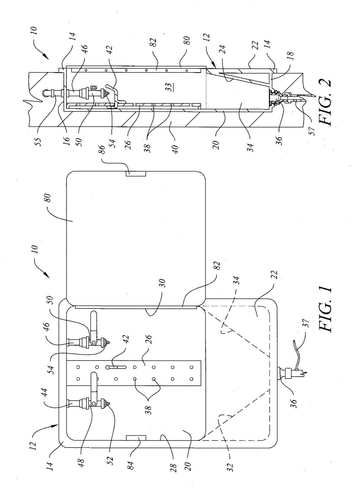
[0018]Referring to an embodiment of the invention as depicted in FIGS. 1-2, hemodialysis supply box and CRRT drain cabinet 10 (hereafter “cabinet 10”) comprises body 12 having a partially open front surrounded by flange 14. As shown in FIG. 2, the back side of flange 14 abuts against a forwardly facing surface of wall 40 whenever cabinet 10 is installed inside a recess in wall 40. As depicted in this embodiment, body 12 is a substantially rectangular box that further comprises top wall 16, bottom wall 18, back wall 20, side walls 28, 30, and front wall 22 that shields drain 36 beneath door 80. Inclined interior walls 24, 32, 34 satisfactorily extend as high as the top of front wall 22 and are intended to channel water, treatment fluids, waste fluids or other liquids flowing downwardly through interior space 33 (FIG. 2) toward drain 36 disposed in bottom wall 18. If needed, trap primer 37 or another similarly effective device can also be provided beneath drain 36 to prevent waste gas...


PUM


Abstract

A wall-mounted hemodialysis supply box and drain cabinet for use in continuous renal replacement therapy is provided that comprises a corrosion-resistant enclosure defining an interior space having a forwardly facing opening with a hinged door, at least one water-supply valve, at least one variable height bag holder, a bottom wall with a drain, and a plurality of inclined inside walls configured to channel waste water and treatment fluids into the drain. A sprayer hose attachment for use in washing down and cleaning the interior space is also disclosed.

Description

CROSS-REFERENCE TO RELATED APPLICATIONS[0001]This application claims the benefit of U.S. Provisional Application No. 62 / 521,842, filed Jun. 19, 2017 and U.S. Provisional Application No. 62 / 527,105, filed Jun. 30, 2017.TECHNICAL FIELD[0002]This invention relates to a hemodialysis supply box and drain cabinet that is useful to healthcare workers performing hemodialysis or continuous renal replacement therapy (CRRT) on a patient in a hospital, intensive care unit or other medical care facility or dialysis center within which such procedures are performed. In various embodiments of the invention, the subject supply box and cabinet is fabricated from stainless steel or another similarly effective material and is mountable in or on a wall of a patient care area within a medical treatment facility. The invention preferably comprises at least one water inlet valve, at least one fluid drain through a bottom portion of the cabinet, at least one wash-down hose for use in flushing the interior ...

Claims


Application Information

Patent Timeline
Patent Type & Authority Applications(United States)
IPC IPC(8): A61M1/16A61M1/34
CPCA61M1/1621A61M1/1601A61M1/341A61M2209/082A61M1/1668A61M1/1694A61M1/1656A61M1/34A61M2209/10A61B50/10A61B2050/105
Inventor MORETTI, CAMILLABEMETICH, ALEXANDRAMILLER, KELLY
Owner HKS INC
Why Eureka
Try Eureka