Pneumatic brake booster having a connecting pin

Active Publication Date: 2018-12-20
CONTINENTAL TEVES AG & CO OHG
View PDF6 Cites 0 Cited by
  • Summary
  • Abstract
  • Description
  • Claims
  • Application Information

AI Technical Summary

Benefits of technology

[0026]In a further development, the housing shells can be moved into abutment in the axial direction with respect to one another, at their radially outer edge sections, in order to provide better support against vacuum forces during braking operation.
[0027]Tools for producing the housing shell are as a result considerably simplified and the production costs and

Problems solved by technology

For the positioning of such clips, tools are required which ineffectively take up a large amount of space.
In addition, in the case of surface-coated housing shells the surface coating o

Method used


Image

  • Pneumatic brake booster having a connecting pin
  • Pneumatic brake booster having a connecting pin
  • Pneumatic brake booster having a connecting pin

Examples


Embodiment Construction

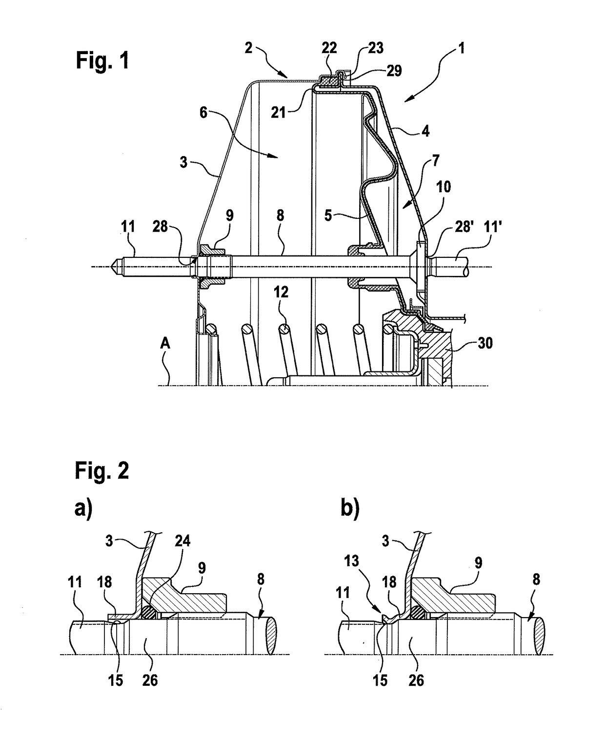
[0039]FIG. 1 shows a partial view of a known embodiment of a pneumatic brake booster 1 of the generic type.

[0040]The booster housing 2 comprises a front housing shell 3 and a rear housing shell 4 which are arranged in series along a central axis A. A working wall 5 is shifted to limited extent along the central axis A, which working wall separates a vacuum chamber 6 from a working chamber 7. For the purpose of sealing the vacuum chamber 6 off from the working chamber 7, a rolling diaphragm 21 is applied partially to the working wall 5. A sealing bead 22, which is clamped in axially and radially between the housing shells 3, 4 is formed onto the radial outer edge of the rolling diaphragm 21, which sealing bead 22 serves to seal the booster housing 2 with respect to the surroundings and to secure the rolling diaphragm 21.

[0041]A connecting pin 8 is arranged axis-parallel with respect to the central axis A in the booster housing 2. In the embodiment shown, the connecting pin 8 projects...


PUM


Abstract

A pneumatic brake booster for a hydraulic motor-vehicle brake system, including a booster housing, having a front and a rear housing shell, and at least one connecting pin, which is arranged in the booster housing such that the at least one connecting pin extends axially parallel to the center axis and which supports the booster housing from the inside by two supporting formations and which protrudes through the booster housing from the inside to the outside on at least one side by an end segment. In order to ensure simple intermediate handling of the brake booster before and during the assembly of the brake system and to improve the durability and corrosion resistance, the housing shells are arranged in such a way that the housing shells are each connected to the connecting pin such that the housing shells are secured against being axially moved apart from each other.

Description

CROSS REFERENCE TO RELATED APPLICATIONS[0001]This application is the U.S. National Phase Application of PCT International Application No. PCT / EP2016 / 064273, filed Jun. 21, 2016, which claims priority to German Patent Application No. 10 2015 212 089.9, filed Jun. 29, 2015, the contents of such applications being incorporated by reference herein.FIELD OF THE INVENTION[0002]The invention relates to a pneumatic brake booster for a hydraulic motor vehicle brake system.BACKGROUND OF THE INVENTION[0003]Such brake boosters are widespread and are known, for example, from WO0061416A1, which is incorporated by reference or WO2004101341A2, which is incorporated by reference.[0004]The booster housing of such brake boosters usually comprises two cup-shaped housing shells which are arranged in series along a brake booster central axis.[0005]Brake boosters of the generic type have connecting pins which are arranged in the booster housing in an axis-parallel fashion with respect to the central axis ...

Claims


Application Information

Patent Timeline
IPC IPC(8): B60T13/567B60T13/573
CPCB60T13/5675B60T13/573
Inventor FALLER, JURGENHERKE, OLIVEREBERHART, RENE PETER
Owner CONTINENTAL TEVES AG & CO OHG
Why Eureka
Try Eureka