Radial Blade Impeller for an Industrial Fan Assembly

a technology of industrial fans and impellers, which is applied in the direction of radial flow pumps, non-positive displacement fluid engines, pump components, etc., can solve the problems of increasing the resistance of the system and static pressure, reducing efficiency and unwanted vibration, and increasing the sound level

Active Publication Date: 2018-12-20
DEKALB BLOWER INC
View PDF0 Cites 2 Cited by
  • Summary
  • Abstract
  • Description
  • Claims
  • Application Information

AI Technical Summary

Benefits of technology

[0005]In one aspect of the present disclosure, an impeller is disclosed. The impeller may include an impeller hub having a cylindrical shape, a hub outer surface and a hub shaft bore, a plurality of blade arms circumferentially spaced about the hub outer surface and extending outward from the hub outer surface, each of the blade arms having a leading arm surface facing a direction of rotation of the impeller and a trailing arm surface opposite the leading arm surface, a plurality of impeller blades, each of the impeller blades corresponding to one of the blade arms and ha

Problems solved by technology

Where the industrial fan assemblies are implemented in high temperature environments, the impeller blades are further subjected to thermal stresses that, along with the other loads and stresses, can cause the impeller blades to change shape from having a formed radius and blade twist for optimum performance, and thereby result in reduced efficiency and unwanted vibration.
These changes can also result in increased sound levels, increased turbulence past the impeller that increases the resistance of the system and the static pressure against which the fan operates.
Th

Method used


Image

  • Radial Blade Impeller for an Industrial Fan Assembly
  • Radial Blade Impeller for an Industrial Fan Assembly
  • Radial Blade Impeller for an Industrial Fan Assembly

Examples


Embodiment Construction

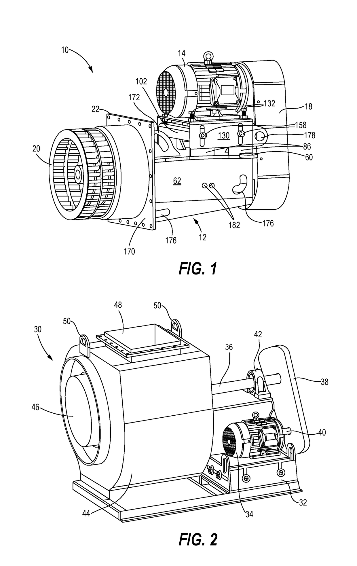
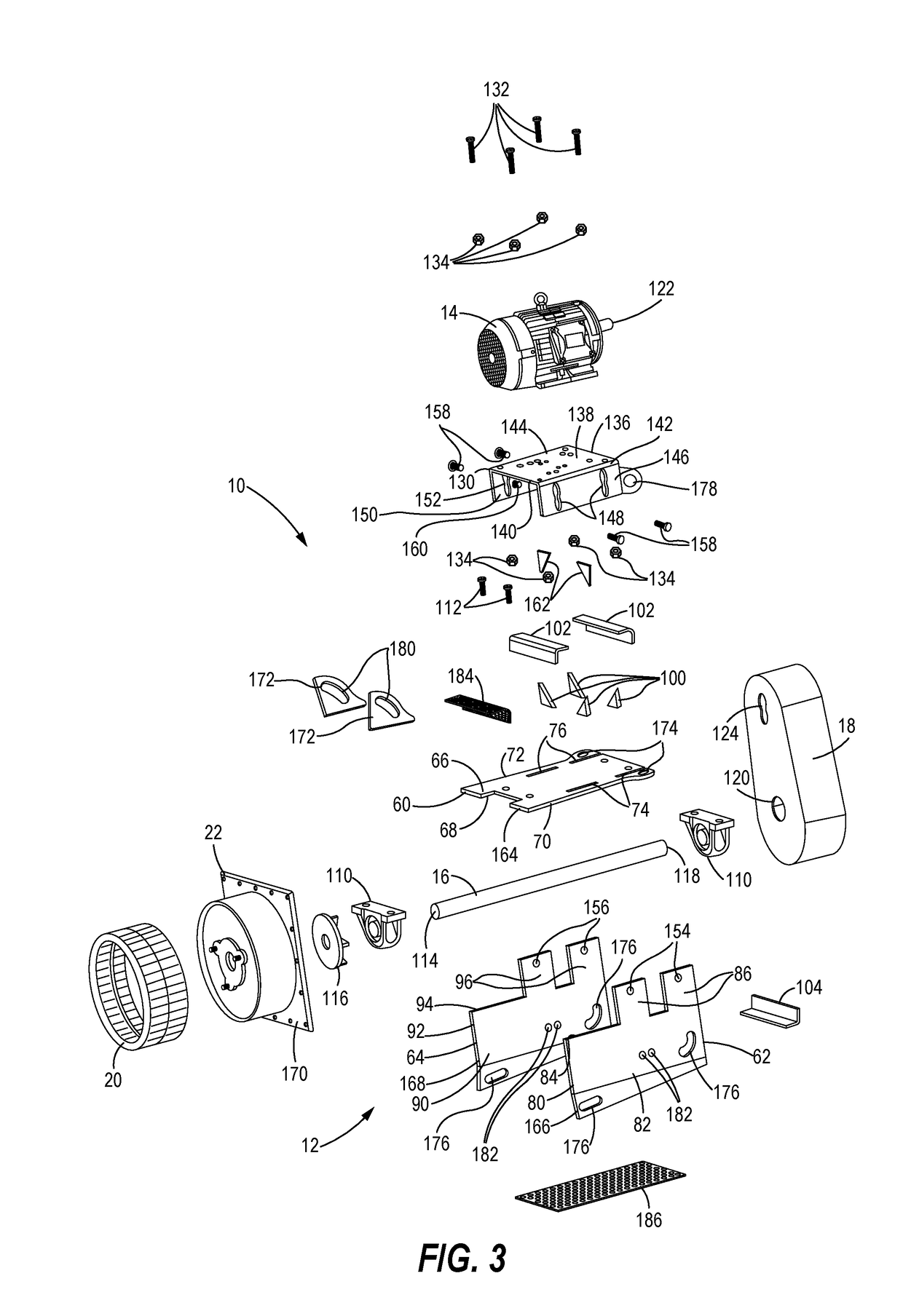
[0034]FIG. 1 illustrates an exemplary configuration of an industrial fan assembly 10 that may be implemented in high temperature applications. The industrial fan assembly 10 may include a fan mount assembly 12 supporting a motor 14, a fan shaft 16 (FIG. 3), and a transmission 18 connecting the motor 14 to the fan shaft 16. The fan assembly 10 further includes an impeller 20, such as the forward curve wheel hub impeller 20 shown in FIG. 1, mounted to an end of the fan shaft 16 opposite the transmission 18. The impeller 20 may be installed within a high temperature area such as a furnace or curing station, while the other components of the industrial fan assembly 10 are disposed external to the high temperature environment. An insulation dam assembly 22 may be positioned on the fan shaft 16 between the fan mount assembly 12 and the impeller 20, and mounted to a wall or other interface between the high temperature and low temperature areas to reduce or prevent heat transfer across the ...


PUM


Abstract

A radial blade impeller for an industrial fan assembly may include a cylindrical impeller hub having a hub outer surface and a hub shaft bore, a plurality of impeller blade assemblies circumferentially spaced about the hub outer surface and extending outward from the hub outer surface. A first sprocket disposed on a first end of the impeller hub engages a lateral edge of each of the impeller blade assemblies and has a plurality of first sprocket teeth extending outward from a first sprocket outer edge. Each of the first sprocket teeth corresponds to one of the impeller blade assemblies and engages and is secured to the first lateral edge of the corresponding one of the impeller blade assemblies. A second sprocket disposed on a second end of the impeller hub has a similar configuration with second sprocket teeth aligning with and engaging opposite lateral edges of the impeller blade assemblies.

Description

TECHNICAL FIELD[0001]The present disclosure relates generally to industrial fan assemblies and, more particularly, to a radial blade impeller for an industrial fan assembly.BACKGROUND[0002]Industrial fan assemblies are used in industrial applications to create fluid flow for processes such as combustion, ventilation, aeration, particulate transport, exhaust, cooling, air-cleaning, drying and air recirculation. Fluid flow is created by rotating an impeller having a plurality of blades to create a reduced pressure at an inlet of the fan assembly to draw air in and an increased pressure at an outlet of the fan assembly to discharge air back into the operating environment. Typically, an industrial fan assembly includes a mounting structure on which a motor and a fan shaft are mounted. A transmission connects the motor to the shaft to convert rotation of a motor shaft of the motor into corresponding rotation of the fan shaft. The impeller is mounted on or otherwise operatively connected ...

Claims


Application Information

Patent Timeline
IPC IPC(8): F04D29/28F04D29/30
CPCF04D29/30F04D29/282F04D17/16F04D29/263F04D29/329F04D29/34F04D29/388F04D29/626
Inventor JOHANSEN, ERIC J.
Owner DEKALB BLOWER INC
Why Eureka
Try Eureka