Transmission control device detecting change of shift level and vehicle having the same

a technology of transmission control and shift level, which is applied in the direction of engine starters, instruments, etc., can solve the problems of difficult installation in a narrow space, degrading fuel efficiency, and affecting the safety of drivers, and achieves the effect of easy detection of the change of the shift level

Active Publication Date: 2018-12-20
KYUNG CHANG IND
View PDF10 Cites 1 Cited by
  • Summary
  • Abstract
  • Description
  • Claims
  • Application Information

AI Technical Summary

Benefits of technology

[0019]A transmission control device according to the embodiments of the present invention has a structure in which the rotational motion of the shift lever is converted into the linear motion of the slider having magnet disposed therein. Therefore, the magnet sensor is capable of relatively easily detecting the change of the shift level.
[0020]In a vehicle according to the embodiment of the present invention, the transmission control device detects the neutral position, so that it is possible to implement the Idle Stop & Go (ISG) function in the neutral position.
[0021]However, the effect of the present invention is not limited to the above description and can be variously extended without departing from the scope and spirit of the present invention.

Problems solved by technology

Since the engine is undoubtedly working even in the idling state, fuel is consumed, so that not only fuel efficiency is degraded, but also air pollution is caused.
In the case of the manual shift control device, in an existing device that implements the (ISG) function, a sensor which detects the state where a vehicle is not traveling has a large and complex structure and is thus difficult to install in a narrow space.
Therefore, the prior art document still does not propose a transmission control device which can be installed in a narrow space.

Method used


Image

  • Transmission control device detecting change of shift level and vehicle having the same
  • Transmission control device detecting change of shift level and vehicle having the same
  • Transmission control device detecting change of shift level and vehicle having the same

Examples


Embodiment Construction

[0030]Hereinafter, preferred embodiments in accordance with the present invention will be described with reference to the accompanying drawings. The preferred embodiments are provided so that those skilled in the art can sufficiently understand the present invention, but can be modified in various forms and the scope of the present invention is not limited to the preferred embodiments.

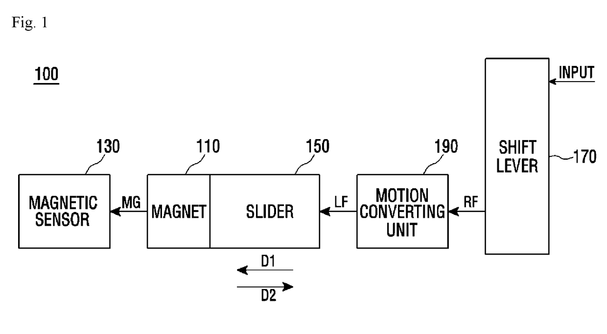
[0031]FIG. 1 is a block diagram showing a transmission control device according to embodiments of the present invention.

[0032]Referring to FIG. 1, a transmission control device 100 may include a magnet 110, a magnetic sensor 130, a slider 150, a shift lever 170, and a motion conversion member 190. According to the embodiment, the transmission control device 100 may further include a housing.

[0033]The magnet 110 can generate a magnetic field (MG). In the embodiment, the magnet 110 may be a permanent magnet. In another embodiment, the magnet 110 may be an electromagnet. In this case, the strength of the ...


PUM


Abstract

A transmission control device may be provided that includes a magnet, a magnetic sensor, a slider, a shift lever, and a motion conversion member. The magnetic sensor is fixed to a predetermined position and measures a magnetic field which changes according to a relative position with respect to the magnet. The magnet is disposed at one end of the slider. The shift lever rotates to a position according to a shift level by user operations. When the shift lever rotates, the motion conversion member converts a rotational motion of the shift lever into a linear motion, and moves the slider in a first direction.

Description

BACKGROUNDField[0001]The present disclosure relates to a transmission control device, and more particularly to a transmission control device of a manual transmission, which detects the change of a shift level, and a vehicle including the same.Description of the Related Art[0002]A transmission converts the power generated by an engine into a rotational force. In an internal combustion engine, a Revolution Per Minute (RPM) band for obtaining the maximum torque is different from a Revolution Per Minute (RPM) band for obtaining the maximum output. Therefore, it is necessary to select an appropriate shift position in accordance with the speed of a vehicle or an engine RPM and to convert the power into the rotational force.[0003]Here, a transmission control device controls the transmission. The transmission control device is divided into a manual shift control device (a manual transmission) and an automatic shift control device (an automatic transmission). The manual shift control device ...

Claims


Application Information

Patent Timeline
Patent Type & Authority Applications(United States)
IPC IPC(8): F16H59/04F16H63/50F16H25/18G01D5/14
CPCF16H59/044F16H63/50F16H25/18G01D5/145F16H2059/0269F16H59/10F16H59/68F16H61/0213F16H61/0251F02N11/0814F16H59/105F16H2059/706Y02T10/40
Inventor HONG, HYEONG SEOK
Owner KYUNG CHANG IND
Why Eureka
Try Eureka