
Method for feeding electrical power into an electric supply network

a technology of electrical power and electrical supply, applied in the direction of machines/engines, mechanical equipment, greenhouse gas reduction, etc., can solve the problems of insufficient expansion, insufficient stability of the grid, and inability to achieve the optimal stabilization of the grid by synchronous generators, so as to reduce the rotational speed, small effect on the power at the operating point, and strong variation in rotational speed

Active Publication Date: 2018-12-27
WOBBEN PROPERTIES GMBH
View PDF5 Cites 8 Cited by
  • Summary
  • Abstract
  • Description
  • Claims
  • Application Information

AI Technical Summary

Benefits of technology

This patent describes a system for generating electricity from wind. By using a rotor with adjustable blades and a delay in the tracking of the reference system, the system can react to changes in the grid voltage and produce stable power. This results in better control and performance of the generator.

Problems solved by technology

However, such solutions are possibly not extensive enough, particularly when the large power plants with directly coupled synchronous generators still present in the electrical supply grid are declining in terms of their dominance, or in the most extreme case are disappearing completely.
However, even in the case of such solutions, stability problems in the grid can remain, become greater or reoccur.
It should first be noted that also stabilization of the grid by synchronous generators does not consistently function in an ideal manner.

Method used


Image

  • Method for feeding electrical power into an electric supply network
  • Method for feeding electrical power into an electric supply network
  • Method for feeding electrical power into an electric supply network

Examples


Embodiment Construction

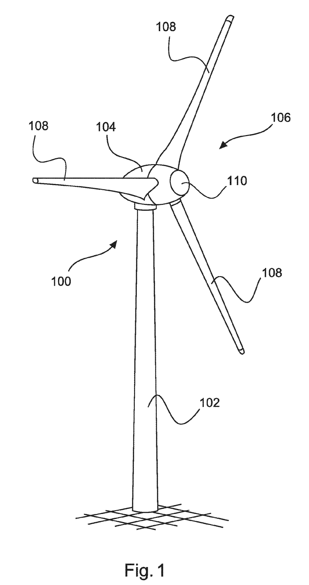
[0102]FIG. 1 shows a wind power installation 100 with a tower 102 and a nacelle 104. Arranged on the nacelle 104 is a rotor 106 with three rotor blades 108 and a spinner 110. During operation, the rotor 106 is set in rotation by the wind and thereby drives a generator in the nacelle 104.

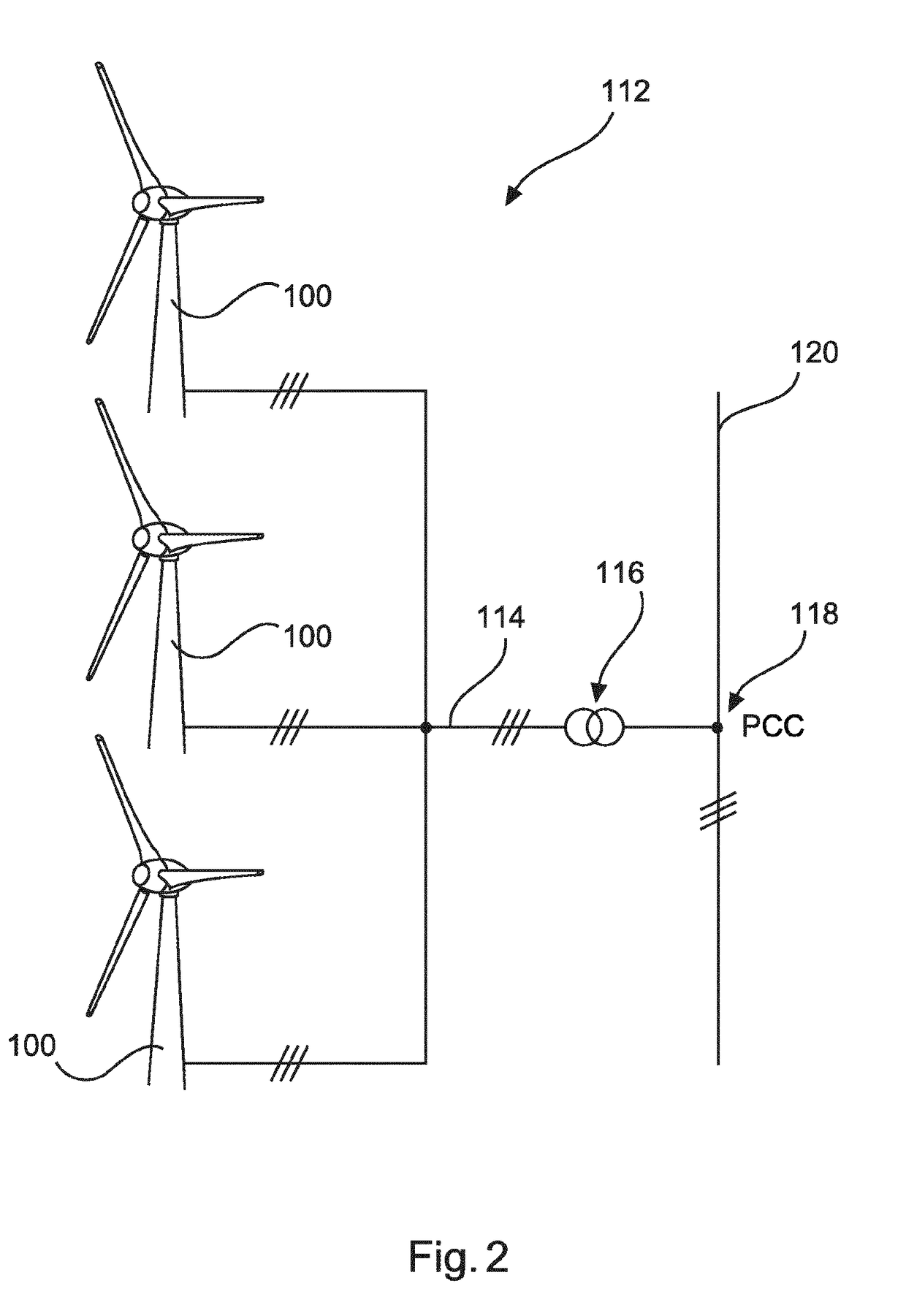
[0103]FIG. 2 shows a wind farm 112 having, for example, three wind power installations 100, which may be identical or different. The three wind power installations 100 are thus representative of basically any desired number of wind power installations of a wind farm 112. The wind power installations 100 provide their power, namely, in particular, the generated current, via an electrical farm grid 114. In this case, the respectively generated currents or powers of the individual wind power installations 100 are added together and a transformer 116, which steps up the voltage in the farm, is usually provided in order to then feed into the supply grid 120 at the feed-in point 118, which is also generall...


PUM


Abstract

A method for feeding electrical power, by a one wind power installation, a power plant or a generation plant, into an electrical supply grid is provided. The grid has a grid voltage having a grid frequency at a grid connection point. In the method a reference system having a reference frequency, a reference phasor having a reference angle, and a reference amplitude of an output voltage are specified. The reference angle revolves at the reference frequency and the reference frequency substantially corresponds to the grid frequency. A phase angle between the output voltage and the grid voltage is specified and an infeed angle is determined. The output voltage is generated having a voltage amplitude depending on the reference amplitude, a frequency depending on the reference frequency and the infeed angle. Tracking of the behavior of the grid voltage is delayed by the reference system.

Description

BACKGROUNDTechnical Field[0001]The present invention relates to a method for feeding electrical power into an electrical supply grid. The present invention furthermore relates to a wind power installation for carrying out such a method and the invention also relates to a wind farm having a plurality of wind power installations for carrying out such a method, or a power plant or a generation unit having at least one wind power installation and a combination having stores, controllable consumers and / or other regenerative generators. The invention also relates to an arrangement of a plurality of wind power installations or a plurality of wind farms for feeding in at a plurality of grid connection points.Description of the Related Art[0002]It is known to feed electrical power into an electrical supply grid, such as, for example, into the European interconnected grid system, using wind power installations. For the feed-in, such wind power installations conventionally use frequency invert...

Claims


Application Information

Patent Timeline
Patent Type & Authority Applications(United States)
IPC IPC(8): F03D9/25F03D9/11H02J3/38
CPCF03D9/257F03D9/11H02J3/386F05B2270/337H02J2300/28H02J3/381Y02E10/76Y02E10/72Y02E70/30H02J3/40H02J3/38
Inventor BROMBACH, JOHANNES
Owner WOBBEN PROPERTIES GMBH
Learn More