
Stabilized thermal energy output system

a technology of thermal energy output and stable temperature, which is applied in the direction of indirect heat exchangers, electric heating, lighting and heating apparatus, etc., can solve the problems of limiting the tolerance of graphite medium to temperatures well below that of the graphite medium itself, and affecting the operation of the maximum operating temperature of the graphite medium,

Inactive Publication Date: 2018-12-27
KELVIN THERMAL ENERGY INC
View PDF0 Cites 16 Cited by
  • Summary
  • Abstract
  • Description
  • Claims
  • Application Information

AI Technical Summary

Benefits of technology

The controller in this system regulates the flow of fluids to make sure they are safe for downstream equipment and cool down to a safe temperature. This ensures that the fluid returning from the equipment is cool enough for mixing and cooling purposes.

Problems solved by technology

Although the graphite storage medium can theoretically operate at temperatures in excess of 3000° C., a problem exists when the temperature of the output heat transfer fluid (used to extract and deliver thermal energy) is in excess of what the downstream equipment (typically traditional connecting components and heat exchangers limited to about 700° C.) can tolerate.
For example, the use of high temperature steel components becomes difficult or unstable at about 850° C. and advancements in turbine and heat exchanger designs still limit their tolerance to temperatures well below that of the graphite medium itself.
Thus, the maximum operating temperature of the graphite medium is limited by the thermal tolerance of the components located at the output and downstream of the storage system.
A further limitation to the maximum operating temperature of the graphite medium relates to the thermal resistance of the supporting structure.
Due to the weight of the graphite core, the support structure under the core must be constructed of stronger materials which typically have lower insulating capabilities.

Method used


Image

  • Stabilized thermal energy output system
  • Stabilized thermal energy output system
  • Stabilized thermal energy output system

Examples


Embodiment Construction

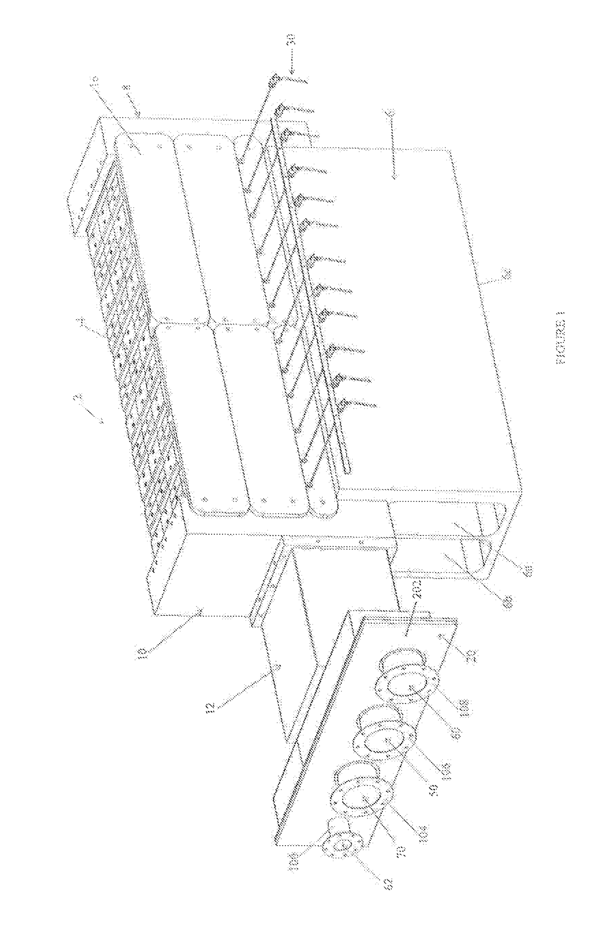
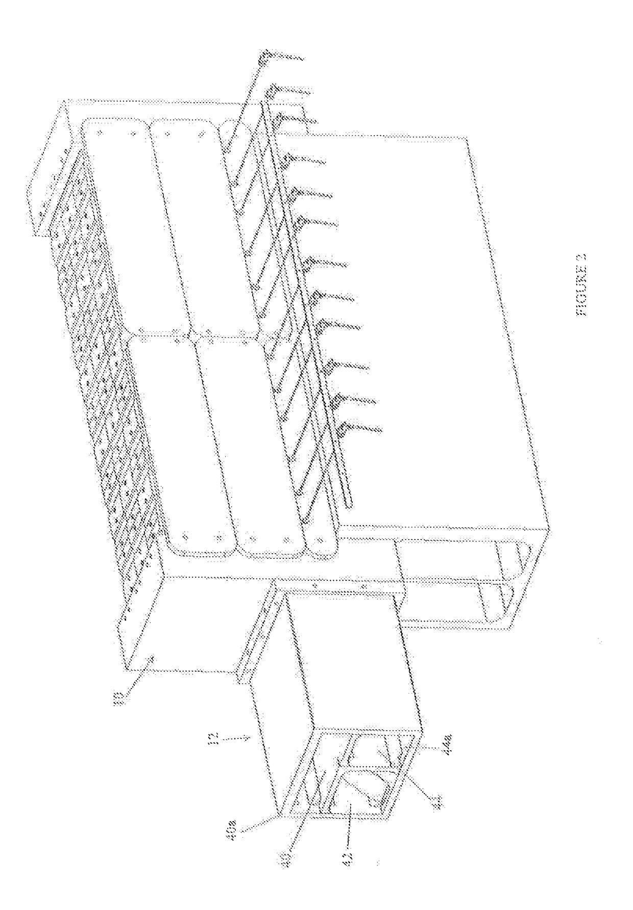
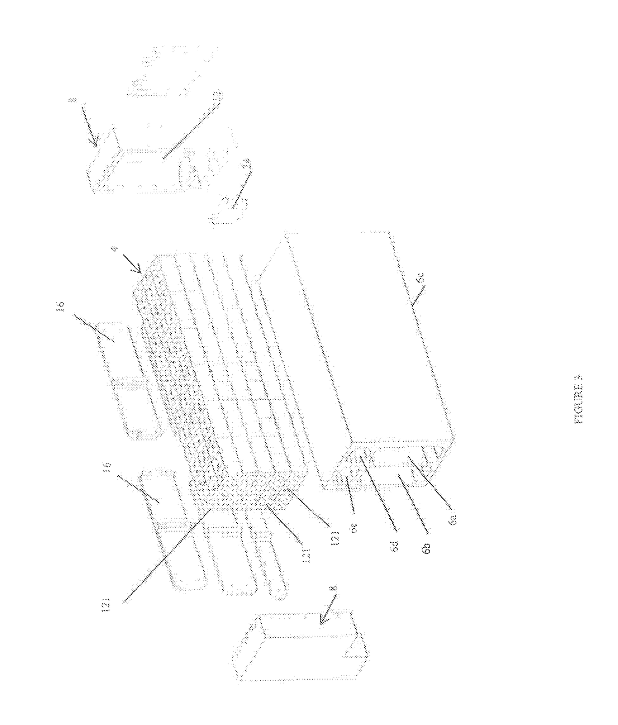
[0035]FIG. 1 generally shows the high temperature thermal energy storage and transfer arrangement 2 where enveloping insulation and an associated containment vessel have not been shown. In one embodiment, the containment vessel is a bulk shipping container sized for shipping by truck. The working components of the storage and transfer arrangement are clearly illustrated. The graphite storage segment 4 rest on top of a support block 6 that is made of a high temperature ceramic material. The ceramic material is chosen to provide minimal thermal expansion and contraction at cycling high temperatures and to provide insulating properties with respect to conductive heat transfer through the support block which could receive an insulating coating as a further thermal barrier between the support block and the graphite body.

[0036]The preferred embodiment will be described with respect to a high temperature graphite storage segment 4, however, the invention involves support of such a high tem...


PUM


Abstract

A thermal energy storage system utilizes a high temperature storage segment having flow passages extending through the storage segment whereby a working fluid can extract energy from the storage system for powering conventional downstream equipment. A mixing manifold cooperates with an outlet manifold for reducing the temperature of the working fluid to a temperature safe for the downstream equipment. The mixing manifold, an outlet manifold, an inlet manifold and a support base for the high temperature storage segment, are all of a high temperature tolerant material allowing the high temperature storage segment to operate at temperatures in excess of 1000° C. and preferably to temperatures above 1400° C. The temperature of the working fluid provided to the conventional equipment can be managed to be below a maximum temperature which in many cases may be about 700° C.

Description

FIELD OF THE INVENTION[0001]The present invention relates to thermal energy storage and transfer arrangements and, in particular, relates to such arrangements that include a thermal energy storage segment and energy transfer fluid.BACKGROUND OF THE INVENTION[0002]For many years, graphite based thermal energy storage systems typically heated with electrical heating elements, have been recognized as being conceptually capable of operating at ultra high temperatures. An example of a graphite based thermal energy storage device is disclosed in Applicant's earlier applications, namely, Canadian Patent Application No. 2,780,437 and United States Patent Application Publication No. 2015 / 0219404 A1. PCT Publication No. WO 2015 / 085357 A1, filed by Graphite Energy N.V also discloses a graphite based system.[0003]Although the graphite storage medium can theoretically operate at temperatures in excess of 3000° C., a problem exists when the temperature of the output heat transfer fluid (used to e...

Claims


Application Information

Patent Timeline
IPC IPC(8): F28D20/00G05D23/13H05B1/02
CPCF28D20/00G05D23/13H05B1/0297F28D20/0056F28D2020/0069F28D2020/0078F28D2020/0086F28F21/02F28F21/04F28D2020/0021F28D2020/0026Y02E60/14F28F9/02B01F25/42
Inventor AHADI, AMIRHOSSEINLYNCH, GEORGECROCKER, ADAMSUTHERLAND, STEPHEN
Owner KELVIN THERMAL ENERGY INC
Learn More