Supercharge Your Innovation With Domain-Expert AI Agents!

Method of and apparatus for activating fuel cell

a fuel cell and apparatus technology, applied in the direction of fuel cells, electrical apparatus, electrochemical generators, etc., can solve the problem of high cost required for the activation of the fuel cell, and achieve the effect of high cos

Active Publication Date: 2018-12-27
HONDA MOTOR CO LTD
View PDF1 Cites 0 Cited by
  • Summary
  • Abstract
  • Description
  • Claims
  • Application Information

AI Technical Summary

Benefits of technology

The present invention provides a method and apparatus for activating a fuel cell using a small amount of anode and cathode media, resulting in a low cost activation. This is in contrast to current methods which require large amounts of materials and result in high costs. The technical effects include a simplified and cost-effective method for activating fuel cells.

Problems solved by technology

Therefore, high cost is required for activation of the fuel cell.

Method used


Image

  • Method of and apparatus for activating fuel cell
  • Method of and apparatus for activating fuel cell
  • Method of and apparatus for activating fuel cell

Examples


embodiment examples

Embodiment Example 1

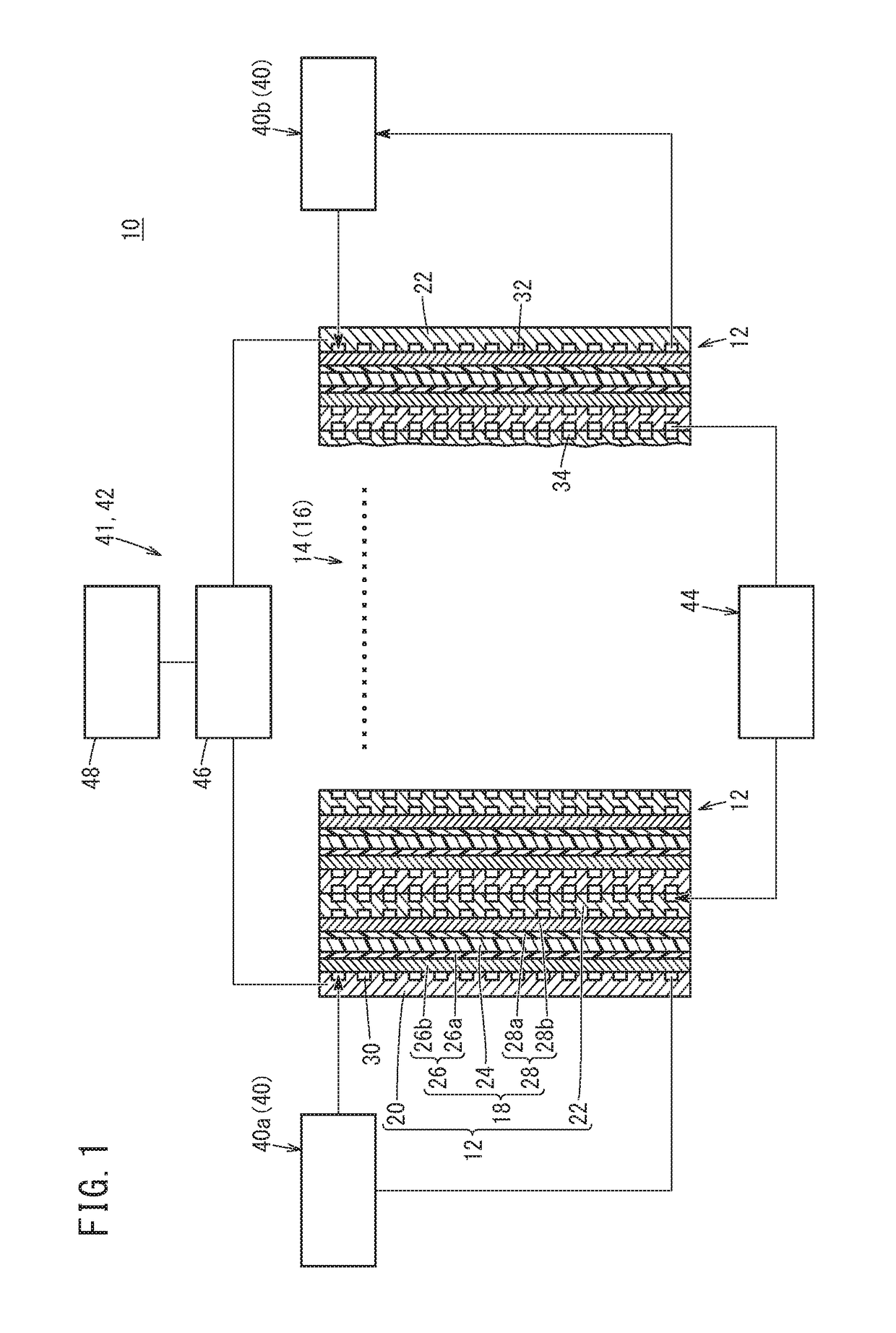
[0080]A stack 14 was assembled by stacking ten power generation cells 12 each having an MEA 18 with an effective power generation area of 100 cm2. This stack 14 was set to the activation apparatus 10, and the energizing step was performed. In the energizing step, the temperature of the stack 14 was regulated to 40° C. by the temperature regulating unit 44. Further, by the first supply unit 40a, a hydrogen gas as the anode gas having the dew point of 75° C. was supplied to the anode 26 at the flow rate of 5 NL / min., and by the second supply unit 40b, a nitrogen gas as the cathode gas having the dew point of 80° C. was supplied to the cathode 28 at the flow rate of 20 NL / min.

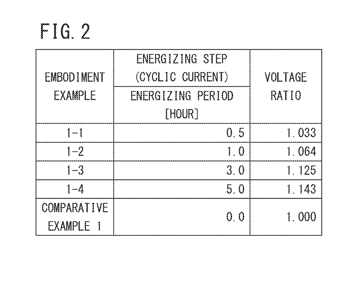
[0081]Thereafter, after it was confirmed that the average cell potential of the cathode 28 becomes substantially constant at 0.06 V, the anode 26 and the cathode 28 were energized by the energizing unit 41, and the magnitude of the electrical current applied between the anode 26 and the cathode...

embodiment example 2

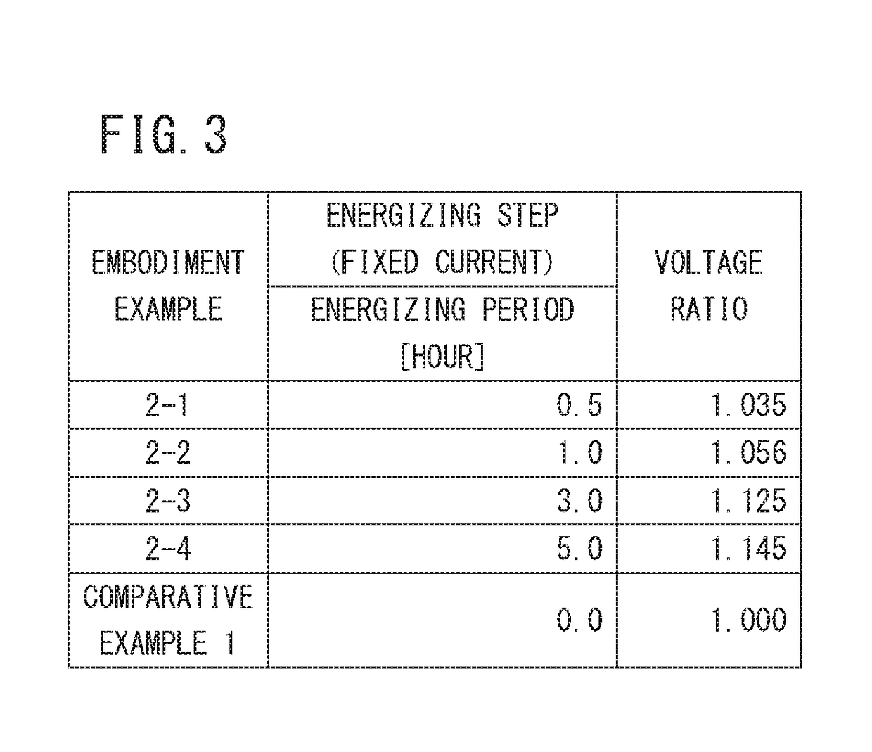
[0086]Stacks 14 according to the embodiment example 2 was produced in the same manner as the embodiment example 1 except that, as the energization current applied between both electrodes, a fixed current at 3 A was used instead of the above cyclic current. That is, as shown in FIG. 3, by using different energization periods of the fixed current, the stacks 14 according to embodiment examples 2-1 to 2-4 were obtained. For each of the stacks 14, the voltage ratio was calculated in the same manner as in the case of the embodiment example 1, and the result is shown in FIG. 3 as well.

[0087]As shown in FIG. 3, also in the stacks 14 of the embodiment examples 2-1 to 2-4 where the fixed current is used as the energizing current applied between the electrodes, the voltage ratios which are substantially the same as that of the stack 14 of the embodiment example 1 where the cyclic current is used as the energizing current applied between the electrodes were obtained. That is, in any of the sta...

embodiment example 3

[0088]Stacks 14 according to the embodiment examples 3-1 to 3-10 were produced in the same manner as in the case of the embodiment example 2 except that the magnitude of the fixed current as the energizing current applied between the electrodes (energizing current value) is changed as shown in FIG. 4. These embodiment examples 3-1 to 3-10 will also be referred to as the embodiment example 3, collectively. It should be noted that the stacks 14 of the embodiment examples 3-6 were produced under substantially the same conditions as the stack 14 of the embodiment example 2-1.


PUM


Abstract

A method of activating a fuel cell includes an energizing step. In the energizing step, a hydrogen gas as an anode gas is supplied to an anode, and an inert gas as a cathode gas is supplied to a cathode to produce a potential difference between the anode and the cathode. In this state, current is applied between the anode and the cathode.

Description

CROSS-REFERENCE TO RELATED APPLICATION[0001]This application is based upon and claims the benefit of priority from Japanese Patent Application No. 2017-124220 filed on Jun. 26, 2017, the contents of which are incorporated herein by reference.BACKGROUND OF THE INVENTIONField of the Invention[0002]The present invention relates to a method of activating a fuel cell including an electrolyte membrane of solid polymer, an anode provided on one surface of the electrolyte membrane, and a cathode provided on the other surface of the electrolyte membrane. Further, the present invention relates to an apparatus for activating the fuel cell.Description of the Related Art[0003]For example, a method of activating a fuel cell disclosed in Japanese Laid-Open Patent Publication No. 2006-040869 is known. In this activation method, anode medium such as methanol solution is supplied to an anode of the fuel cell, and cathode medium such as air is supplied to a cathode. While such media are supplied, ener...

Claims


Application Information

Patent Timeline
IPC IPC(8): H01M8/04225H01M8/1007H01M8/04029H01M8/04701
CPCH01M8/04225H01M8/1007H01M8/04029H01M8/04701H01M2008/1095H01M8/04302H01M8/04126H01M8/0488H01M8/04268Y02E60/50
Inventor TSUGE, HODAKAKATO, TAKASHIYAMADA, TADAAKISATO, KOICHIRO
Owner HONDA MOTOR CO LTD
Features
  • R&D
  • Intellectual Property
  • Life Sciences
  • Materials
  • Tech Scout
  • Unparalleled Data Quality
  • Higher Quality Content
  • 60% Fewer Hallucinations
Learn More