Determination of geometrical information about a medical treatment arrangement comprising a rotatable treatment radiation source unit

a radiation source unit and geometric information technology, applied in the field of geometric information determination of a medical treatment arrangement including a rotatable treatment radiation source unit, can solve the problems of inaccurate geometric information provided by an igrt system, the direction of the central axis of the radiation beam can be unsteady, and the additional devices for image-guided radiation therapy (igrt) may also be misaligned or adjusted

Active Publication Date: 2019-01-03
OPTINAV SP ZOO
View PDF79 Cites 9 Cited by
  • Summary
  • Abstract
  • Description
  • Claims
  • Application Information

AI Technical Summary

Benefits of technology

[0010]It is an object of the present invention to provide a method of determining geometrical information about a medical treatment arrangement including a rotatable treatment radiation source unit, wherein the geometrical information is determinable without assumptions regarding the position and orientation of the rotation axis or of any of the rotation axes of the arrangement. In particular, not only isocenter position(s), but also other geometrical information are determined from the determined rotation axis / axes and angles. For example, the method is applicable to arrangements having an electronic portal imaging devices (EPID), but also to radiotherapy simulators or IGRT systems like a system with kV cone beam computed tomography (CBCT) imaging. It is a further object to provide a medical treatment arrangement that allows the method to be performed.
[0041]According to an exemplary embodiment of the method, the rotational movement of the rotatable treatment radiation source or of a part of the rotatable treatment radiation source (e.g., of the collimator) is determined by evaluating projection images obtained for in each case at least two rotational positions. The rotation angle between two of these rotational positions may be small and the method steps may be repeated for different pairs or groups of rotational positions so that the rotational movement is analyzed based on images obtained for a plurality of pairs or groups of rotational positions. This allows for the determination of the movement of the rotation axis as well for the determination of at least one of the isocenters mentioned above.
[0056]According to an aspect of the invention, the orientation of the average rotation axis is determined by minimizing errors of the different orientations with respect to the average rotation axis. In the minimization procedure, the errors with respect to potential average rotation axes can be calculated and the average rotation axis is identified for which the errors are minimal. For example, a least square method can be applied for minimization.

Problems solved by technology

Also, the position and performance of additional elements like imaging devices of the arrangement may cause inaccuracies.
In addition, the direction of the central axis of the radiation beam can unsteadily move because of aging of bearing mechanisms, miscalibration of collimator jaws, tongue-and-groove effect, misalignment of the radiation source unit rotation axis or of the collimator rotation axis.
Also, misadjustment of the radiation source position and beam instability may cause this effect.
Similarly, additional devices for image-guided radiation therapy (IGRT) may also be misaligned or misadjusted.
In any case, the accuracy of the geometric information provided by an IGRT system is limited by its geometric stability as well as its precise position and alignment in relation to the radiation source.
In particular, flexing or sagging of the imaging system under its own weight during gantry rotation results in inaccuracies of the positions of the radiation source and / all of the image detector that detects radiation from the radiation source.
However, the tools used for performing the method may also introduce uncertainties and inaccuracies, e.g., stemming from a mechanical imprecision of the positions of the marker in the phantom, erroneous positioning of the phantom, assumptions made for performing the method and processing of electronic images obtained.
In particular, the method is based on assumptions regarding the isocenter position(s) and these assumptions might be incorrect or imprecise.

Method used


Image

  • Determination of geometrical information about a medical treatment arrangement comprising a rotatable treatment radiation source unit
  • Determination of geometrical information about a medical treatment arrangement comprising a rotatable treatment radiation source unit
  • Determination of geometrical information about a medical treatment arrangement comprising a rotatable treatment radiation source unit

Examples


Embodiment Construction

[0069]As mentioned above, a plurality of modules, namely the phantom and the calibration module, are used for the determination of the geometrical information about the arrangement. This does not exclude the use of at least one further module, such as a module attached to the image detector for determining the image detector position and image scale (in particular the pixel size of the matrix of pixels of the detector). If the pixel size is known in advance, this module need not to be used and can be omitted. The image detector orientation can be determined using the phantom.

[0070]In the following, an arrangement is described that includes three modules. However, the module which is attached to the image detector can be omitted in other exemplary embodiments.

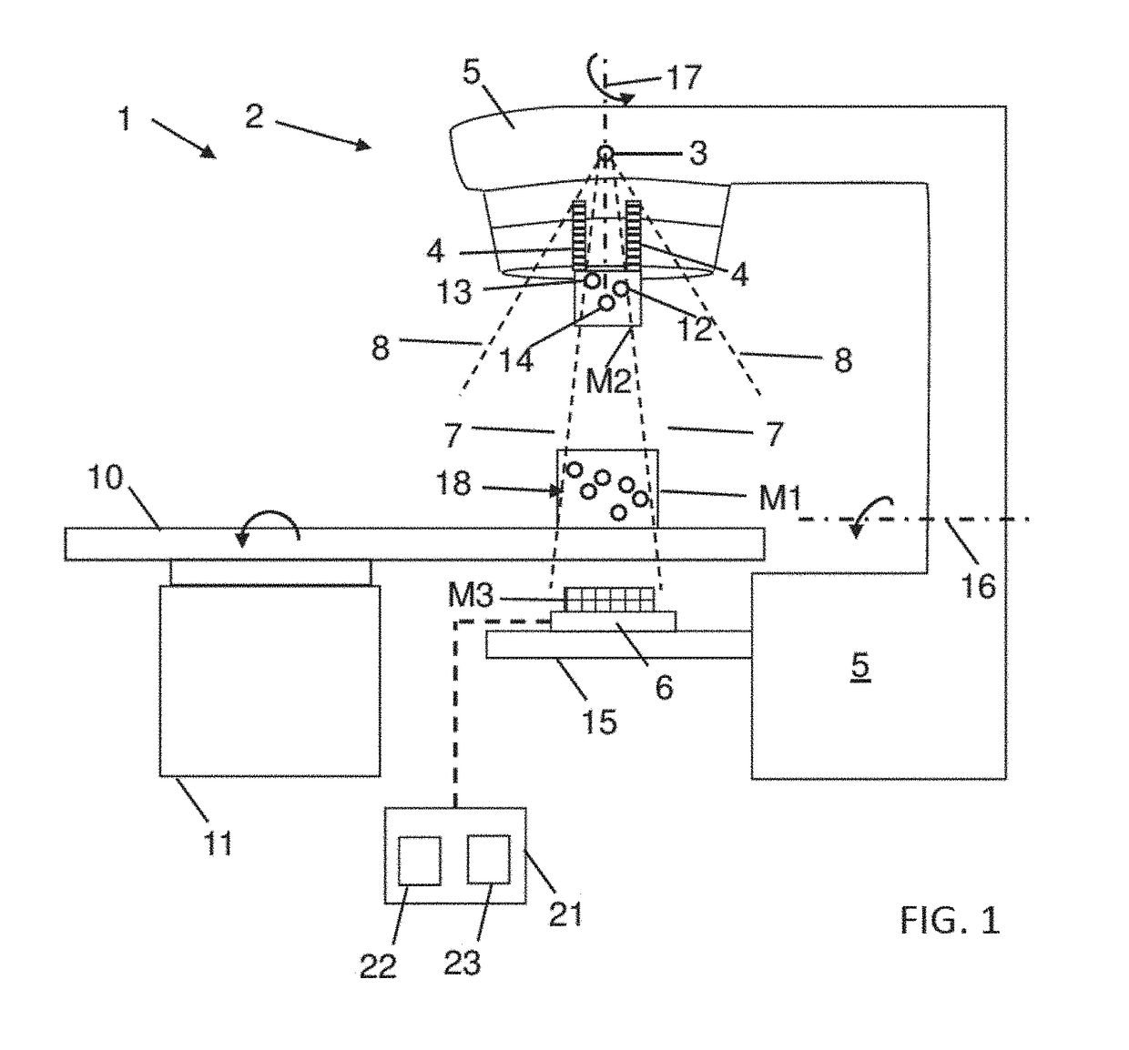
[0071]FIG. 1 schematically shows a medical treatment arrangement 1 including a radiation source unit 2, an image detector 6 and a patient support 10 in the form of a patient table. The radiation source unit 2 includes a radiatio...


PUM


Abstract

A method for determining geometrical information about a medical treatment arrangement that includes a rotatable treatment radiation source unit is provided. The method includes attaching a phantom to a patient support of the medical treatment arrangement, attaching a calibration module to the rotatable treatment radiation source unit to permit the calibration module to rotate together with the rotatable treatment radiation source unit when the rotatable treatment radiation source unit is rotated, obtaining for each of a plurality of rotational positions of the rotatable treatment radiation source unit a projection image of the phantom and of the calibration module by an image detector, while a part of the calibration module is positioned in a radiation propagation zone between the rotatable treatment radiation source unit and the image detector, evaluating the images, obtaining an evaluation result, and determining geometrical information about the medical treatment arrangement from the evaluation result.

Description

CROSS REFERENCE TO RELATED APPLICATIONS[0001]This application claims priority from European patent application EP 17 178 405.1, filed Jun. 28, 2017, the entire content of which is incorporated herein by reference.TECHNICAL FIELD[0002]The invention relates to the determination of geometrical information about a medical treatment arrangement including a rotatable treatment radiation source unit. In particular, the invention relates to a method of determining the geometrical information and to a medical treatment arrangement.BACKGROUND[0003]Medical treatment arrangements including a rotatable treatment radiation source unit are known. For example, gantry type arrangements are known (for example as disclosed by EP 2 450 083 A1) which include a radiation source unit attached to a rotatable gantry, a patient support (such as a patient table) and an image detector which can be used for calibration purposes. During tests or calibration, which include the determination of geometrical informa...

Claims


Application Information

Patent Timeline
Patent Type & Authority Applications(United States)
IPC IPC(8): A61N5/10
CPCA61N5/1075A61N5/1081A61N5/1039A61N2005/1076A61N2005/1097A61B6/58A61B6/582A61B6/583A61B6/584A61N5/10A61N5/1048A61N5/1082
Inventor TULIK, MONIKAKABAT, DAMIANKYCIA, RADOSLAWLATALA, ZBIGNIEWTABOR, ZBISLAW
Owner OPTINAV SP ZOO
Why Eureka
Try Eureka