LED lamp

a technology of light-emitting diodes and led lamps, which is applied in the direction of refractors, light-emitting semiconductor devices for light sources, etc., can solve the problems of inability to completely cut off light rays with undesired wavelengths, band-pass filters tend to be inability to exert light blocking (cutoff) functions, and often emerg

Active Publication Date: 2019-01-03
PHOENIX ELECTRIC CO
View PDF4 Cites 1 Cited by
  • Summary
  • Abstract
  • Description
  • Claims
  • Application Information

AI Technical Summary

Benefits of technology

[0013]According to yet another aspect of the present invention, a light emitting diode lamp is provided that includes a light emitting diode, a band-pass filter, a light shield and a light angle adjuster. The band-pass filter has a light cutoff function to cut off a light ray with a specific wavelength included in light rays emitted from the light emitting diode. The light shield blocks at least part of one or more of the light rays emitted from the light emitting diode when the one or more of the light rays are incident on the band-pass filter at one or more incident angles of greater than a maximum incident angle up to which the band pass filter is capable of exerting the light cutoff function. The light angle adjuster allows the unblocked rest of the one or more of the light rays to be incident on the band-pass filter at one or more incident angles of less than or equal to the maximum incident angle. And the light shield is a shielding tube having a tubular shape. The light angle adjuster is a lens. The light emitting diode is mounted to one end of the shielding tube while the band pass filter is mounted to the other end of the shielding tube. The lens is mounted to an internal space of the shielding tube.
[0014]According to further yet another aspect of the present

Problems solved by technology

However, it was found that the band-pass filter tends to be unable to exert a light blocking (cutoff) function with respect to light rays incident on the band-pass filter at incident angles of greater than a predetermined angle (this tendency wil

Method used


Image

  • LED lamp
  • LED lamp
  • LED lamp

Examples


modification 1

[0068](Modification 1)

[0069]As shown in FIG. 4, at least one of light shielding members 70, 72 and 74 may be added, as a constituent element, to the light emitting diode lamp 10 according to the aforementioned practical example. The light shielding members 70, 72 and 74 are provided for preventing the light emitting diode 20 from being directly seen when the light emitting diode lamp 10 is seen at an angle parallel to the rotational axis RCL of the paraboloid of revolution (i.e., from the front side of the light emitting diode lamp 10). It should be noted that the material, of which the light shielding members 70, 72 and 74 are made, is not limited to a specific material as long as the light shielding members 70, 72 and 74 can block light rays emitted from the light emitting diode 20. For example, metal, opaque resin, ceramic material or so forth can be assumed as the material of the light shielding members 70, 72 and 74.

[0070]The lengths of the light shielding members 70, 72 and 74...

modification 2

[0072](Modification 2)

[0073]Moreover, the heat sink 50 and a light shielding member 78 may be integrated unlike the configuration shown in FIG. 4 that the light shielding members 70, 72 and 74 provided separately from the heat sink 50 are mounted in place. As shown in FIG. 5, at least part of the heat sink 50, located above the light emitting diode 20, is protruded toward the reflective surface 34 so as to form a step 76, as the light shielding member 78, on the light emitting diode mounted lateral face 52 of the heat sink 50 as seen in a cross-sectional view along the up-and-down direction. Accordingly, it is possible to achieve advantageous effects similar to those achieved by forming the light shielding members 70, 72 and 74 provided separately from the heat sink 50 as shown in FIG. 4. Additionally, the light absorbing material may be disposed on the surface of the step 76 in opposition to the light emitting diode 20 in order to avoid a situation that light rays, when striking th...

modification 3

[0074](Modification 3)

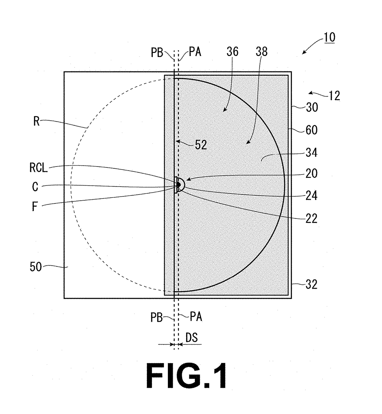
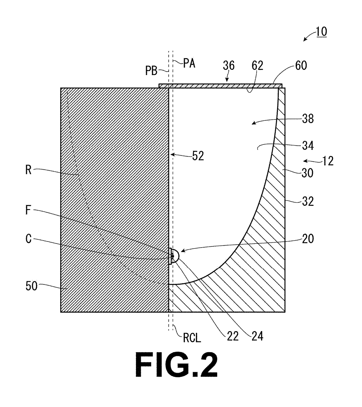
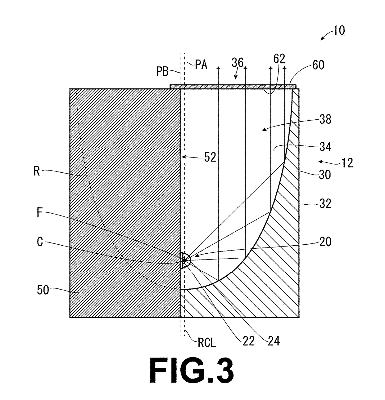
[0075]Furthermore, FIG. 6 shows another example of integrating the heat sink 50 and the light shielding member 78. The light emitting diode mounted lateral face 52 of the heat sink 50 may be formed to slant as seen in a cross-sectional view along the up-and-down direction. This will be specifically explained. The light emitting diode mounted lateral face 52 is shaped to slant with respect to the rotational axis RCL as seen in the cross-sectional view along the up-and-down direction such that the position of the emission center C of the light emitting diode 20 is matched with that of the focal point F of the paraboloid of revolution defining the reflective surface 34, while the opening 36-side end (the upward end) of the light emitting diode mounted lateral face 52 is at least located in a position corresponding to the emission center C of the light emitting diode 20. Accordingly, part of the light emitting diode mounted lateral face 52, located above the light ...


PUM


Abstract

A light emitting diode lamp is composed of a light emitting diode, a band-pass filter and a light angle adjuster. The filter has a light cutoff function to cut off a light ray with a specific wavelength. The light angle adjuster allows the light rays emitted from the diode to be incident on the filter at incident angles of less than or equal to a maximum incident angle up to which the filter is capable of exerting the light cutoff function. The light angle adjuster is a reflector. The diode is mounted to a bottom portion. The filter is mounted to an opening. On an imaginary cross section including the optical axis, an angle formed between the optical axis and a straight line is less than or equal to the maximum incident angle, the straight line connects the emission center and an edge of the opening.

Description

CROSS REFERENCE TO RELATED APPLICATION[0001]This application claims the priority of Japanese Patent Applications No. 2017-126851 filed on Jun. 29, 2017 and No. 2017-133172 filed on Jul. 6, 2017, which are incorporated by reference herein.BACKGROUND OF THE INVENTIONField of the Invention[0002]The present invention relates to a light emitting diode lamp (LED lamp) that is efficiently restricted from emitting, for instance, visible light rays.Background Art[0003]Light emitting diodes have advantages that the power consumption thereof is lower and the life thereof is longer compared to well-known incandescent lamps (e.g., halogen lamps). With enhancement in awareness of ecology by demanders, the usage fields of the light emitting diodes have been rapidly expanding as one of the measures for energy saving. Especially, the light emitting diodes have been increasingly used as relatively compact light sources used as sensors and so forth.[0004]For example, Japan Laid-open Patent Application...

Claims


Application Information

Patent Timeline
IPC IPC(8): F21V9/00F21V13/08F21V13/12F21V11/16F21V13/02F21V29/503F21V7/06F21V29/70
CPCF21V9/00F21V13/08F21V13/12F21V11/16F21V13/02F21V29/503F21V7/06F21V29/70F21Y2115/10F21Y2103/00F21V5/04F21V19/001F21K9/20F21V7/0008F21V7/043F21V9/08F21V13/14F21V29/504
Inventor GOUDA, TETSUYAYAMASHITA, KENICHI
Owner PHOENIX ELECTRIC CO
Why Eureka
Try Eureka