
Control apparatus of heat exchanging system

a control apparatus and heat exchange technology, applied in mechanical devices, machines/engines, transportation and packaging, etc., can solve the problems of decreased temperature of air (i.e. warmed air) supplied to the interior of the vehicle, discomfort of passengers in the vehicle,

Active Publication Date: 2019-01-10
TOYOTA JIDOSHA KK
View PDF2 Cites 0 Cited by
  • Summary
  • Abstract
  • Description
  • Claims
  • Application Information

AI Technical Summary

Benefits of technology

The invention is about a control system for a heat exchanging system that prevents the core flow rate from decreasing below the desired level. This is important because a decrease in core flow rate can result in discomfort for the people in the vehicle. The control system achieves this by reducing the heater pump duty ratio before the engine pump duty ratio, which ensures that the amount of water flowing through the exhaust heat recovery device is not reduced below the necessary level to prevent overheating. This means that the exhaust heat recovery device is protected from overheating and can still function properly.

Problems solved by technology

Thus, persons in the vehicle may feel discomfort.
As described above, when the core flow rate decreases below the requested core flow rate, the temperature of the air (i.e., the warmed air) supplied to the interior of the vehicle may decrease and thus, the person(s) in the vehicle may feel discomfort.
Therefore, also in this case, the temperature of the air (i.e., the warmed air) supplied to the interior of the vehicle may decrease and thus, the person(s) in the vehicle may feel discomfort.
As a result, an amount of the heat exchanging water flowing through the exhaust heat recovery device decreases.
When the amount of the heat exchanging water flowing through the exhaust heat recovery device is small, the exhaust heat recovery device may overheat.
Thus, the amount of the heat exchanging water flowing through the exhaust heat recovery device is unlikely to decrease below the amount of the heat exchanging water necessary to flow through the exhaust heat recovery device for preventing the exhaust heat recovery device from overheating.

Method used


Image

  • Control apparatus of heat exchanging system
  • Control apparatus of heat exchanging system
  • Control apparatus of heat exchanging system

Examples


Embodiment Construction

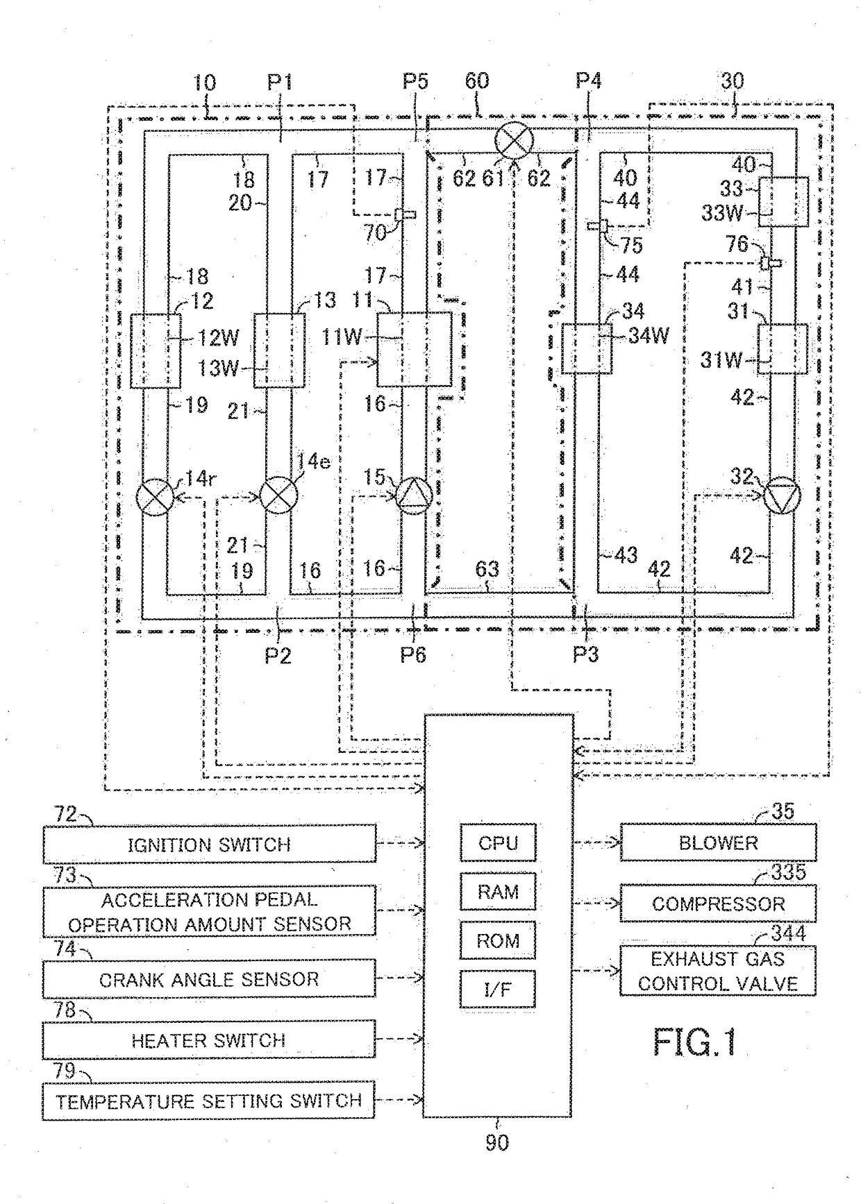
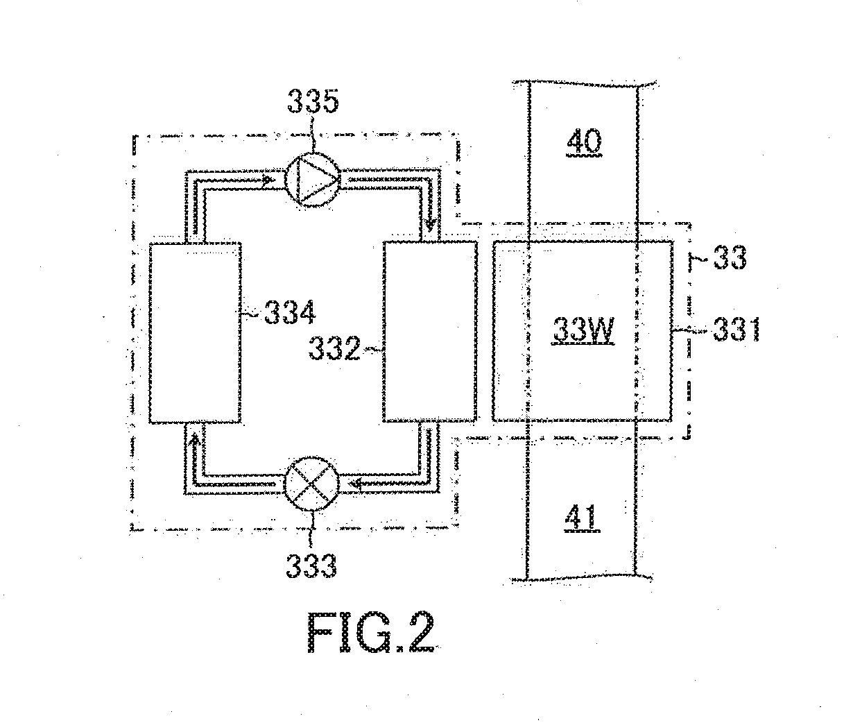
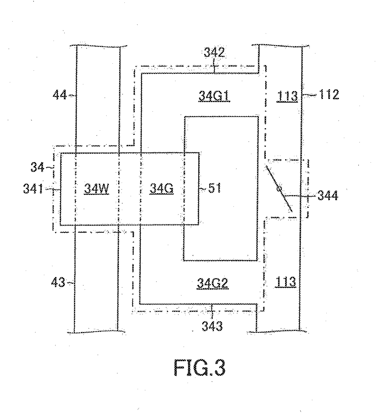
[0053]Below, a control apparatus of a heat exchanging system according to an embodiment of the invention, will be described with reference to the drawings. As shown in FIG. 1, the heat exchanging system, to which the control apparatus according to the embodiment of the invention is applied, includes an engine cooling system 10 and a heater core heating system 30. The cooling system 10 cools an internal combustion engine 11 by heat exchanging water. The heating system 30 heats a heater core 31 by the heat exchanging water. Hereinafter, the control apparatus according to the embodiment will be referred to as “the embodiment apparatus”.

[0054]The cooling system 10 includes an engine water passage for circulating the heat exchanging water. The heating system 30 includes a heater water passage for circulating the heat exchanging water.

[0055]The heat exchanging system includes a connection system 60 for connecting the engine water passage of the cooling system 10 and the heater water passa...


PUM


Abstract

A control apparatus of a heat exchanging apparatus according to the invention executes a control for activating a connection system to connect an engine water passage to a heater water passage and then, executes a control for decreasing a heater pump duty ratio and a control for decreasing an engine pump duty ratio when the control for decreasing the heater pump duty ratio and the control for decreasing the engine pump duty ratio are requested to be executed in order to control a core flow rate to a requested core flow rate and an engine flow rate to a requested engine flow rate after the engine water passage is connected to the heater water passage by the connection system.

Description

BACKGROUNDField[0001]The invention relates to a control apparatus of a heat exchanging system including a heater core heating system for heating a heater core for heating air supplied to an interior of a vehicle for warming the interior of the vehicle by heat exchanging water, and an engine cooling system for cooling an internal combustion engine by the heat exchanging water.Description of the Related Art[0002]A control apparatus of the heat exchanging system including the heater core heating system and the engine cooling system is known (for example, see JP 2016-107979 A). The heater core heating system of the known heat exchanging system includes a heater water passage, through which the heat exchanging water flows, and a heater pump for circulating the heat exchanging water through the heater water passage. Further, the engine cooling system of the known heat exchanging system includes an engine water passage, through which the heat exchanging water flows, and an engine pump for ...

Claims


Application Information

Patent Timeline
Patent Type & Authority Applications(United States)
IPC IPC(8): B60H1/00B60H1/12F01P3/20F01P5/10F01P7/16
CPCB60H1/00885B60H1/12F01P3/20F01P2025/08F01P7/16F01P2060/08F01P5/10B60H1/004B60H1/04B60H1/00892B60H1/025F01P2005/105
Inventor AIKAWA, HIDEFUMIOGURA, YOICHIYANO, MASATOSHIMIYOSHI, YUJIOFUNE, YU
Owner TOYOTA JIDOSHA KK
Learn More