Analog angle sensor accuracy correction program correction method recording medium and servo driver

Active Publication Date: 2010-05-20
TAMAGAWA SEIKI CO LTD
View PDF1 Cites 2 Cited by
  • Summary
  • Abstract
  • Description
  • Claims
  • Application Information

AI Technical Summary

Benefits of technology

[0020]The problem to be solved by the present invention is to provide an analog angle sensor accuracy correction program, correction method, recording medium and servo driver capable of solving the above described problems of the conventional technology, automatically correcting sensor accuracy of a resolver used for motor control of an AC servo motor or the like or an analog angle sensor such as an analog sine wave encoder, thereby suppressing variations in a calculated motor rotation speed value due to the above described pitch error and thereby effectively preventing the motor control response performance from reducing. The present invention is particularly intended to provide an analog angle sensor accuracy correction program, correction method, recording medium and servo driver capable of displaying such a function without the servo driver which drives the motor using any encoder which serves as a reference for other.
[0042]According to the analog angle sensor accuracy correction program, correction method, recording medium and servo driver of the present invention configured as described above, it is possible for an analog angle sensor such as a resolver used to control a motor such as an AC servo motor to suppress variations in the calculated motor rotation speed value due to a pitch error and effectively prevent the motor control response performance from decreasing through an automatic correction of sensor accuracy. Especially, the present invention can achieve such an effect without the servo driver that drives the motor using any encoder that serves as a reference for others.
[0043]That is, the analog angle sensor accuracy correction program or the like of the present invention can reduce current ripples caused by poor sensor accuracy, set a higher control gain and thereby improve the motor control response performance.
[0044]Furthermore, the analog angle sensor accuracy correction program or the like of the present invention requires no special equipment or apparatuses to calculate a correction value and can thereby calculate a correction value at lower cost and in a short time and obtain a desired effect.

Problems solved by technology

As described above, rampage by pitch errors in controlling the motor speed has been coped with by emergency measures such as reducing a control gain, but an adjustment of a control gain naturally has its limitation.
When the servo driver is performing speed control or position control, if there is a variation in the calculated speed value, an accurate deviation from a speed commanded value cannot be calculated and this may cause the control response speed not to be increased.
As a countermeasure for this problem, there is also a method of averaging the calculated speed value, but such a method takes a considerable time until the calculated speed value converges to the actual speed, which delays the response time for speed calculation, ending up reducing the control response speed.
The technology disclosed in above Patent Document 1 considers an offset, phase error and amplitude difference as correction targets, but this cannot cope with a pitch error which is a much more microscopic error.

Method used


Image

  • Analog angle sensor accuracy correction program correction method recording medium and servo driver
  • Analog angle sensor accuracy correction program correction method recording medium and servo driver
  • Analog angle sensor accuracy correction program correction method recording medium and servo driver

Examples


Embodiment Construction

[0078]With reference now to the attached drawings, the present invention will be explained in detail below.

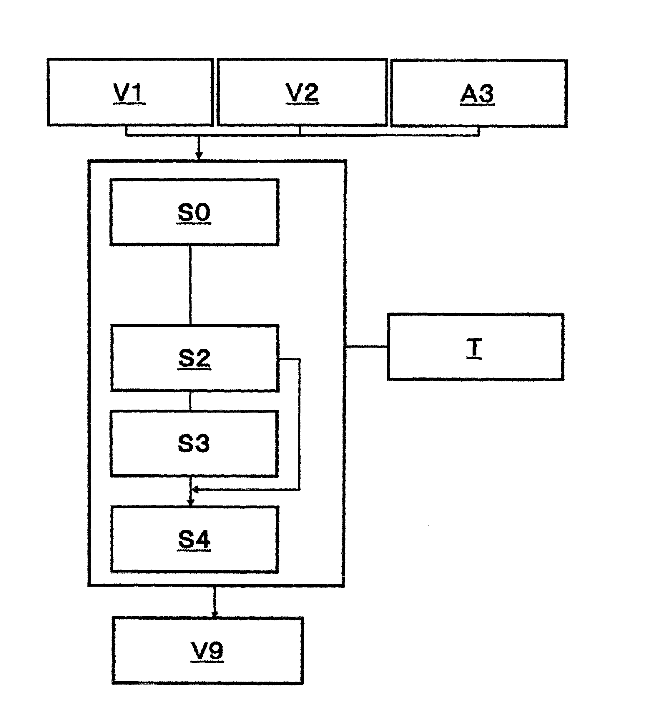
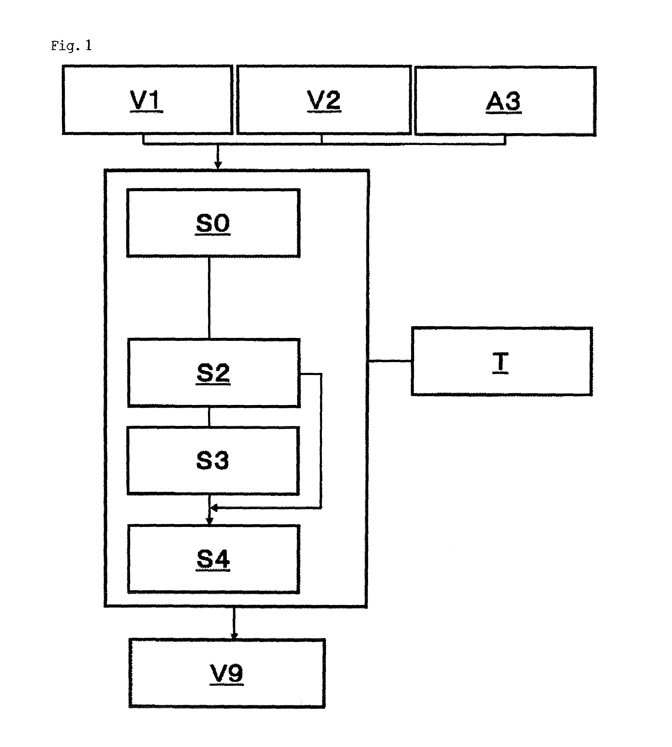
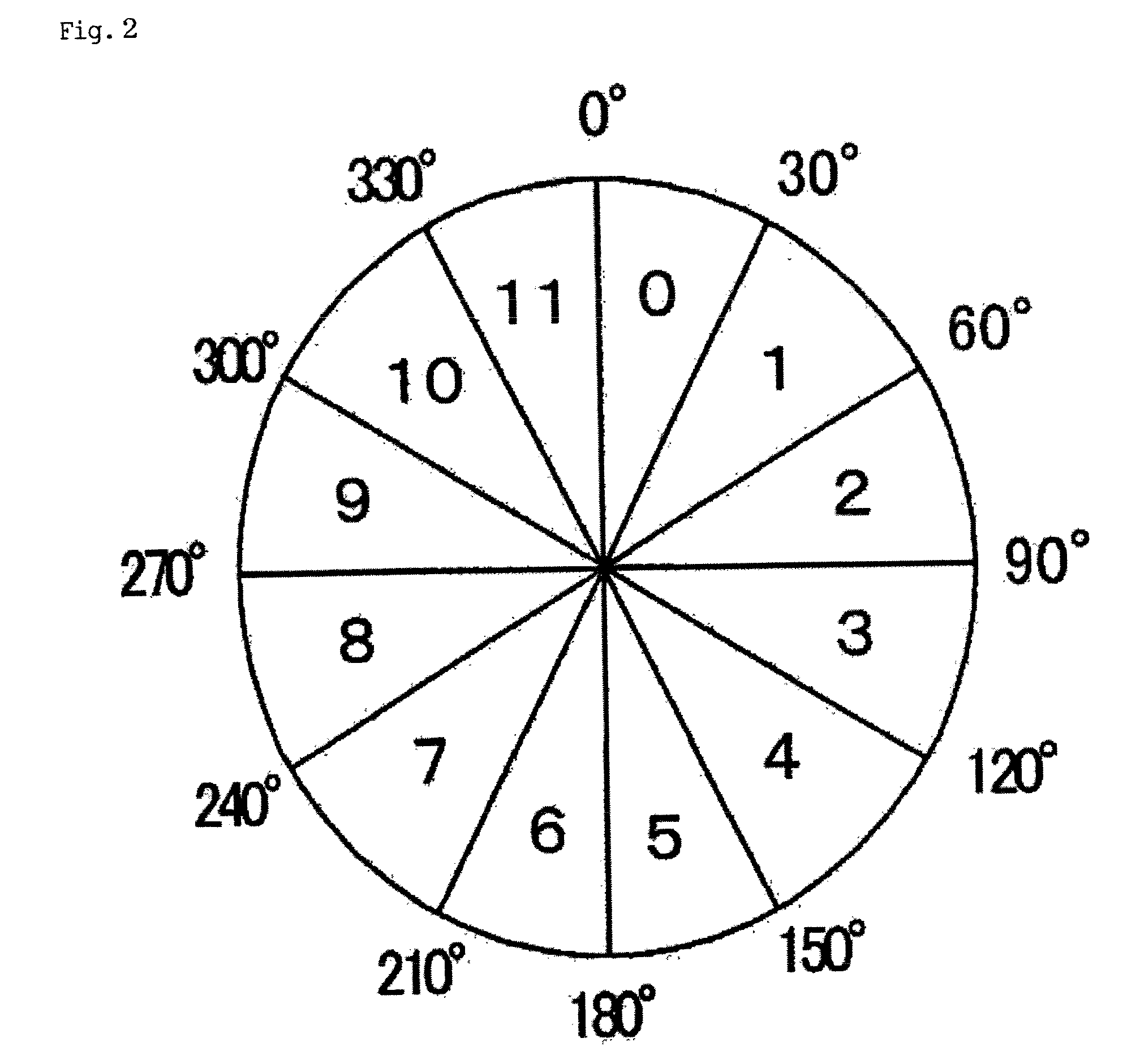
[0079]FIG. 1 is a flow chart showing basic steps of an analog angle sensor accuracy correction program of the present invention. Furthermore, FIG. 2 is a diagram illustrating an example of correction areas used in the analog angle sensor accuracy correction program of the present invention and FIG. 3 is a diagram illustrating the basic configuration and an example of the actual configuration of a correction table corresponding to the correction area example in FIG. 2 used in the analog angle sensor accuracy correction program of the present invention.

[0080]In FIG. 3, the left side shows the basic configuration of correction table, and the right side shows the example of the actual configuration.

[0081]First, the basic principles of the program of the present invention will be explained centered on FIG. 1, followed by explanations of a more specific configuration.

[0082]As shown i...


PUM


Abstract

A sensor accuracy adjustment program for an analog angle sensor used in an AC servomotor control. A step (S3) of applying an adjustment value update processing to adjustment values in adjustment areas in an adjustment table depending on the result of the comparison of the value of a command rate with the value of the rate of an adjustment processing target by using the adjustment table in which changeable adjustment values used for adjustment calculation are arranged for each of the adjustment areas in which the range of a motor shaft rotation angle is divided for use as a unit of an adjustment processing, a step (S0) of applying the adjustment calculation to the target rate value by using the adjustment values after the update, and a step (S4) for judging the state in which the step (S4) is implemented in order to apply the step (S3) to all the adjustment areas of the adjustment table are functioned to the servo driver.

Description

TECHNICAL FIELD[0001]The present invention relates to an analog angle sensor accuracy correction program, correction method, recording medium and servo driver, and more particularly, to an analog angle sensor accuracy correction program or the like for an analog angle sensor such as a resolver and analog sine wave encoder used to control a motor such as an AC servo motor, capable of automatically correcting sensor accuracy without a servo driver which drives the motor using any encoder which serves as a reference for others.BACKGROUND ART[0002]An analog angle sensor such as a resolver is conventionally used as an angle sensor to control an AC servo motor or the like. These sensors send angle information with an analog waveform to a motor control apparatus. Therefore, in order for control software in the control apparatus to use this angle information as a motor angle / speed value, processing of converting the angle information to a digital value is required.[0003]FIG. 8 illustrates a...

Claims


Application Information

Patent Timeline
IPC IPC(8): G01P21/00G01D5/244G01P3/44H02P6/16H02P6/17
CPCG01D5/24452G01P21/02G01P3/489G01D5/2449G01D18/001
Inventor KANAZAWA, SHOUJI
Owner TAMAGAWA SEIKI CO LTD
Why Eureka
Try Eureka