Blade-disc arrangement for a turbomachine

a technology of blade discs and turbomachines, which is applied in the direction of machines/engines, mechanical apparatus, sustainable transportation, etc., can solve the problems of increasing operating temperatures only insufficiently, increasing temperature of discs, etc., and achieve the effect of reducing the application temperature of the discs

a technology of blade discs and turbomachines, which is applied in the direction of machines/engines, mechanical apparatus, sustainable transportation, etc., can solve the problems of increasing operating temperatures only insufficiently, increasing temperature of discs, etc., and achieve the effect of reducing the application temperature of the discs

US20190010825A1Inactive Publication Date: 2019-01-10MTU AERO ENGINES GMBH

Image

  • Blade-disc arrangement for a turbomachine
  • Blade-disc arrangement for a turbomachine
  • Blade-disc arrangement for a turbomachine

Examples


Embodiment Construction

[0027]Further advantages, characteristics and features of the present invention will be clarified in the following detailed description of the examples of embodiment. Of course, the invention is not limited to these exemplary embodiments.

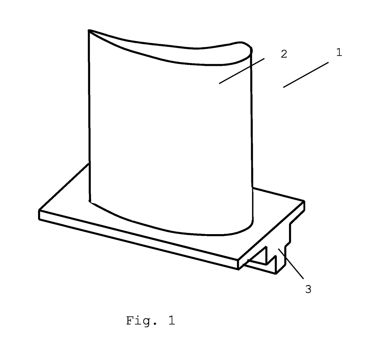
[0028]In a perspective illustration, FIG. 1 shows a blade 1 of a turbomachine, such as, for example, a stationary gas turbine or an aircraft engine that can be connected to a disc of the turbomachine. For this purpose, the blade 1 has a blade root 3 that can be introduced into a groove of a disc. Usually, a plurality of blades 1 are arranged by their respective blade roots 3 in a plurality of grooves 5 on the casing surface of a disc, in order to fasten a plurality of blade elements 2 to the disc. As can also be discerned from the following illustrations of the examples of embodiment, the form of the blade root 3 and of a corresponding complementary groove can be executed in any desired, different form, so that the invention is not limited to a spec...


PUM

PropertyMeasurementUnit
Temperatureaaaaaaaaaa
Thicknessaaaaaaaaaa
Electrical conductivityaaaaaaaaaa

Abstract

The present invention relates to a blade-disc arrangement for a turbomachine having a disc and a plurality of grooves that are arranged in a casing surface of the disc for taking up blades, as well as a plurality of blades with blade roots that are accommodated in the grooves, wherein at least one heat shield element is arranged between at least one blade root and a groove surface of at least one groove, so that there is no direct contact between blade root and disc in the groove region, wherein the heat shield element is formed of a ceramic material, at least in part.

Description

BACKGROUND OF THE INVENTION[0001]The present invention relates to a blade-disc arrangement for a turbomachine, such as, for example, a stationary gas turbine or an aircraft engine. Such blade-disc arrangements have a disc and a plurality of blades that are arranged on the casing surface of the disc. For this purpose, the disc has a plurality of grooves in the casing surface of the disc, in which the blades can be fastened by their blade roots.[0002]In turbomachines, such as stationary gas turbines or aircraft engines, the fluid that flows through is propelled or compressed by blades rotating about an axis of rotation, or the fluid that flows through, by interacting with rotatable blades, propels the blades to rotate about an axis of rotation. For this purpose, turbomachines contain a plurality of blades that are arranged on rotating discs. In order to connect the blades with corresponding rotating discs, blade-disc arrangements are known, in which a plurality of grooves are formed i...

Claims


Application Information

Patent Timeline
10 Jan 2019
Publication
US20190010825A1
IPC
F01D25/08
CPC
F01D25/08; F05D2220/323; F05D2300/2118; F05D2260/231; F05D2240/30; F01D5/3092; Y02T50/60
Inventors
KLOETZER, ALEXANDER