
Method for predicting power demand and controlling ess charge/discharge based on the predicted demand, and apparatus using the same

a technology of energy storage system and power demand, applied in the direction of process and machine control, instruments, computer control, etc., can solve the problems of system not being able to deal with unexpected peak usage, low daily battery usage rate, poor prediction accuracy, etc., to optimize energy consumption and ess operation, improve the accuracy of power demand prediction, and reduce energy consumption and energy costs

Active Publication Date: 2019-01-10
DOOSAN HEAVY IND & CONSTR CO LTD
View PDF10 Cites 9 Cited by
  • Summary
  • Abstract
  • Description
  • Claims
  • Application Information

AI Technical Summary

Benefits of technology

The patent text describes a method for predicting the power demand of a consumer with greater accuracy by analyzing their power consumption pattern. Additionally, the text discusses combining different types of batteries with different charging periods and output characteristics to maximize operational efficiency and reduce peak cuts, which can impact power demand. These improvements can lead to reduced charges and lower usage costs.

Problems solved by technology

Prediction accuracy is typically poor or unreliable using such methods, which do not consider such factors as abnormal states of operation and recent power usage patterns.
However, such charge / discharge scheduling often fails to meet the power demand at a given point in time, such that the system cannot deal with unexpected peak usage.
Further disadvantages include low rates of daily battery usage, and weekend and holiday shutdowns of the energy storage system due to low power demand.

Method used


Image

  • Method for predicting power demand and controlling ess charge/discharge based on the predicted demand, and apparatus using the same
  • Method for predicting power demand and controlling ess charge/discharge based on the predicted demand, and apparatus using the same
  • Method for predicting power demand and controlling ess charge/discharge based on the predicted demand, and apparatus using the same

Examples


Embodiment Construction

[0053]In order to clearly illustrate the present disclosure, parts that are not related to the description are omitted, and the same or similar components are denoted by the same reference numerals throughout the specification.

[0054]Throughout the specification, when a part is referred to as being “connected” to another part, it includes not only a case of being “directly connected” but also a case of being “electrically connected” with another part in between. Also, when a part is referred to “include” a component, it is understood that it further includes other elements, not excludes other elements, unless specifically stated otherwise.

[0055]When one portion is referred to as being “on” other portion, it may be directly on the other portion or may be involved with another portion in between. In contrast, when one portion is referred to as being “directly on” other portion, no other portion is involved in between.

[0056]The terms such as first, second, third, etc. are used to descri...


PUM


Abstract

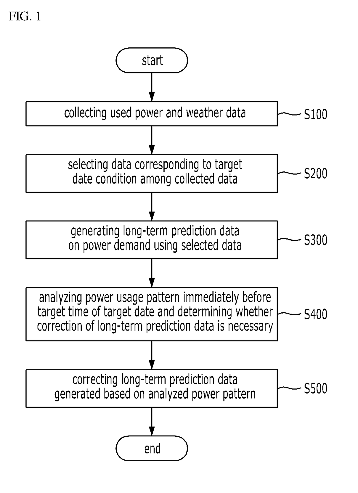
A method for predicting consumer power demand uses power consumption data measured over a long term and a power usage pattern immediately before a target time and for controlling ESS charge / discharge of an ESS based on the predicted power demand. A power demand prediction apparatus using the method includes respective components for collecting weather data and data on power used by the consumer; selecting data points according to a preset condition from among data collected by the data collector based on a specific time span; generating long term prediction data for the power demand in the specific time span based on the selected data points; analyzing a power usage pattern immediately before the specific time span and comparing the power usage pattern with the long-term prediction data, to determine whether prediction data correction is required; and correcting the prediction data based on the power usage pattern when correction is required.

Description

CROSS REFERENCE TO RELATED APPLICATIONS[0001]The present application claims priority to Korean Patent Application No. 10-2017-0086124, filed Jul. 6, 2017, and to Korean Patent Application No. 10-2018-0034443, filed Mar. 26, 2018, the entire contents of which is incorporated herein for all purposes by this reference.BACKGROUND OF THE DISCLOSUREField of the Disclosure[0002]The present disclosure relates generally to the prediction of a power demand and to the charge / discharge control of an energy storage system (ESS) based on the predicted power demand. More particularly, the present disclosure relates to a method for predicting consumer power demand, using power consumption data measured over a long term and a power usage pattern immediately before a target time, and for controlling charge / discharge of an ESS based on the predicted power demand, to enable the ESS to operate according to a more accurate charge / discharge schedule, and to apparatus using the method.Description of the Re...

Claims


Application Information

Patent Timeline
IPC IPC(8): G06F1/28G06N99/00G05B15/02G06F1/26
CPCG06N20/00G06F1/28G06F1/263G05B15/02G06F1/3212Y02D10/00
Inventor YOUN, JU YOUNGPARK, SUNG KURHIE, YOUNG HOON
Owner DOOSAN HEAVY IND & CONSTR CO LTD
Learn More