Al technical title is built by PatSnap Al team. It summarizes the technical point description of the patent document.
a forward error correction and permutation technology, applied in the field of communication system circuits, can solve the problems that significantly affect the overall communication latency, and achieve the effects of optimizing the power consumption, pin efficiency and speed trade-offs, and increasing aggregate bandwidth
Active Publication Date: 2019-01-10
KANDOU LABS
View PDF10 Cites 1 Cited by
Summary
Abstract
Description
Claims
Application Information
AI Technical Summary
This helps you quickly interpret patents by identifying the three key elements:
Problems solved by technology
Method used
Benefits of technology
[0011]In most chip-to-chip, or device-to-device communication systems, communication takes place over a plurality of wires to increase the aggregate bandwidth. A single or pair of these wires may be referred to as a channel or link and multiple channels create a communication bus between the electronic components. At the physical circuitry level, in chip-to-chip communication systems, buses are typically made of electrical conductors in the package between chips and motherboards, on printed circuit boards (“PCBs”) boards or in cables and connectors between PCBs. In high frequency applications, microstrip or stripline PCB traces may be used.
[0012]Common methods for transmitting signals over bus wires include single-ended and differential signaling methods. In applications requiring high speed communications, those methods can be further optimized in terms of power consumption and pin-efficiency, especially in high-speed communications. More recently, vector signaling methods have been proposed to further optimize the trade-offs between power consumption, pin efficiency and noise robustness of chip-to-chip communication systems. In those vector signaling systems, digital information at the transmitter is transformed into a different representation space in the form of a vector codeword that is chosen in order to optimize the power consumption, pin-efficiency and speed trade-offs based on the transmission channel properties and communication system design constraints. Herein, this process is referred to as “encoding”. The encoded codeword is communicated as a group of signals from the transmitter to one or more receivers. At a receiver, the received signals corresponding to the codeword are transformed back into the original digital information representation space. Herein, this process is referred to as “decoding”.
Problems solved by technology
The order in which data and redundancy information are structured into a transmitted data stream can significantly impact overall communication latency, especially if multiple essentially parallel communications channels are involved.
Method used
Image
Click on the blue label to locate the original text in one second.
Reading with bidirectional positioning of images and text.
Examples
example embodiment
[0040]For purposes of explanation and without implying limitation, the reference system for the following descriptions is assumed to have the following characteristics:[0041]Underlying transport providing three sub-channels using ENRZ coding at a 25 Gigasymbol / second rate, equivalent to a 40 picosecond unit interval.[0042]Uncorrected BER in the range of 10E-8 to 10E-9, comprised of both random bit and short burst errors[0043]Corrected FER or BER less than 10E-19[0044]FEC latency of 80 ns or less.
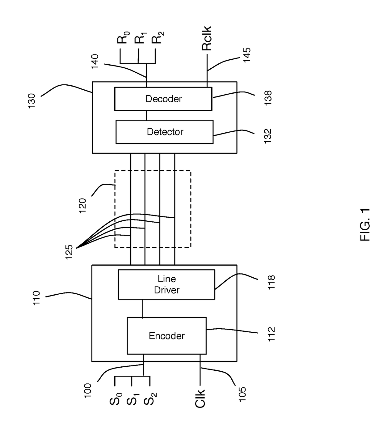
[0045]FIG. 1 is a block diagram of a system that may serve as the physical transport for such a system, with transmitter 110 communicating over a multiwire 125 communications channel 120 to receiver 130.
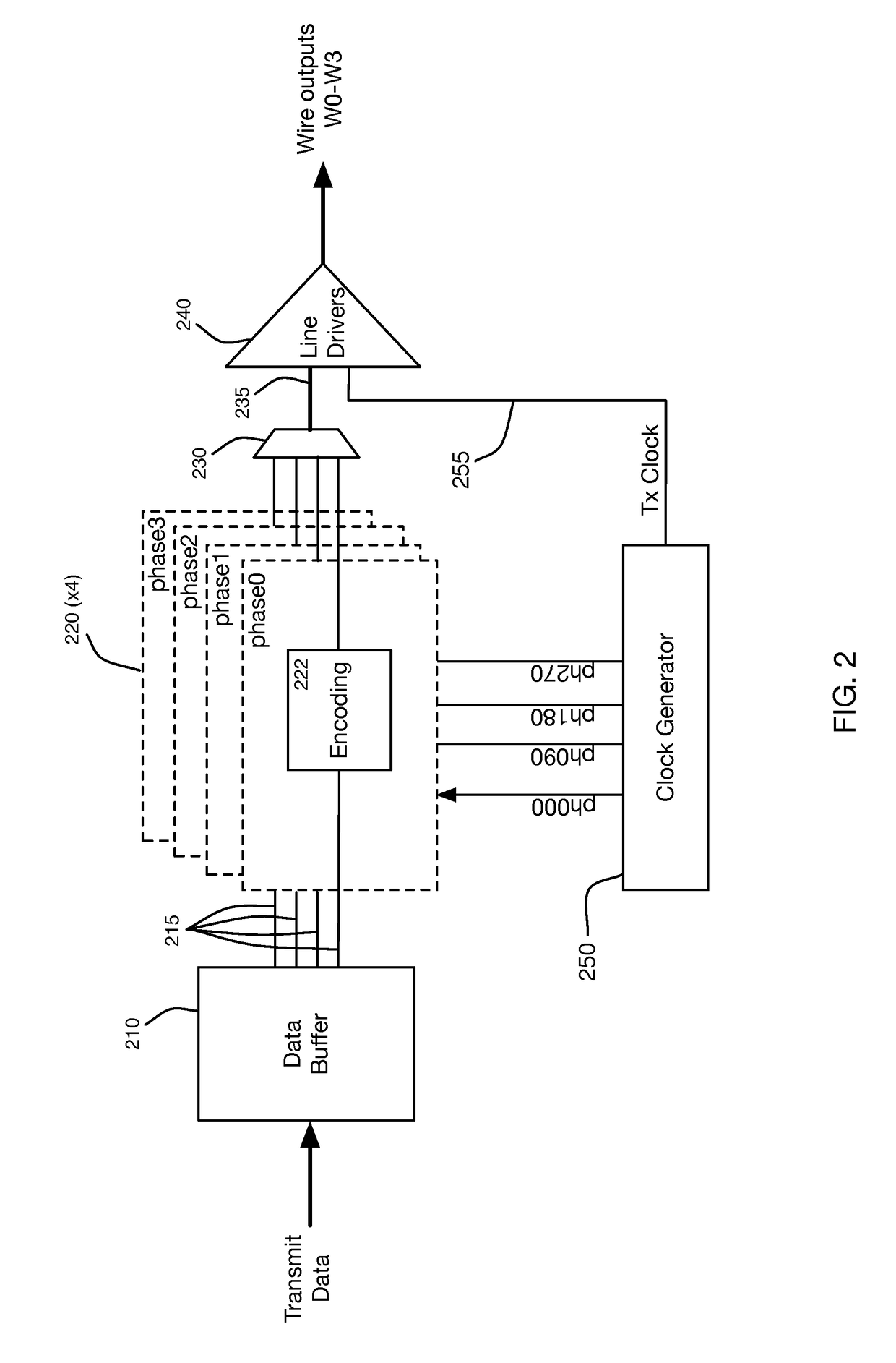
[0046]FIG. 2 illustrates a more detailed block diagram of transmitter 110. In a practical embodiment operating at the example speeds, data will typically be provided using a fairly wide-word interface, to allow a slower transfer rate, with Data Buffer 210 providing the necessary temporary sto...
PUM
Abstract
Methods and systems are described for obtaining a plurality of information bits, and responsively partitioning the obtained plurality of information bits into a plurality of subsets of information bits, generating a plurality of streams of forward error correction (FEC)-encoded bits using a plurality of FEC encoders receiving respective subsets of the plurality of subsets of information bits, providing the plurality of streams of FEC-encoded bits to a plurality of sub-channel encoders, each sub-channel encoder receiving a respective stream of FEC-encoded bits from a different FEC encoder of the plurality of FEC encoders for generating a set of codewords of a vector signaling code, and wherein sequential streams of FEC-encoded bits from a given FEC encoder are provided to different sub-channel encoders for each successively generated set of codewords, and transmitting the successively generated sets of codewords of the vector signaling code over a multi-wire bus.
Description
CROSS-REFERENCE TO RELATED APPLICATIONS[0001]This application claims the benefit of U.S. Provisional Application No. 62 / 530,809, filed Jul. 10, 2017, naming Amin Shokrollahi and Ali Hormati, entitled “Multi-Wire Permuted Forward Error Correction”, which is hereby incorporated herein by reference in its entirety for all purposes.REFERENCES[0002]The following prior applications are herein incorporated by reference in their entirety for all purposes:[0003]U.S. Pat. No. 9,288,089 of application Ser. No. 12 / 784,414, filed May 20, 2010, naming Harm Cronie and Amin Shokrollahi, entitled “Orthogonal Differential Vector Signaling” (hereinafter “Cronie I”).[0004]U.S. patent application Ser. No. 13 / 154,009, filed Jun. 5, 2011, naming Harm Cronie and Amin Shokrollahi, entitled “Error Control Coding for Orthogonal Differential Vector Signaling” (hereinafter “Cronie II”).[0005]U.S. patent application Ser. No. 14 / 253,584, filed Apr. 15, 2014, naming John Fox, Brian Holden, Ali Hormati, Peter Hunt,...
Claims
Application Information
Patent Timeline
Application Date:The date an application was filed.
Publication Date:The date a patent or application was officially published.
First Publication Date:The earliest publication date of a patent with the same application number.
Issue Date:Publication date of the patent grant document.
PCT Entry Date:The Entry date of PCT National Phase.
Estimated Expiry Date:The statutory expiry date of a patent right according to the Patent Law, and it is the longest term of protection that the patent right can achieve without the termination of the patent right due to other reasons(Term extension factor has been taken into account ).
Invalid Date:Actual expiry date is based on effective date or publication date of legal transaction data of invalid patent.
Patent Type & Authority Applications(United States)