Electrostatic chuck

a technology of electrostatic chuck and chuck, which is applied in the direction of basic electric elements, electrical apparatus, and semiconductor devices, etc., can solve the problems of tape burning to be perforated, tape at this position exposed to high temperatures, and adhesive is undetectedly left on each device divided from the wafer, so as to prevent tape burning, suppress tape burning, and prevent tape burning

Active Publication Date: 2019-01-17
DISCO CORP
View PDF7 Cites 4 Cited by
  • Summary
  • Abstract
  • Description
  • Claims
  • Application Information

AI Technical Summary

Benefits of technology

[0008]With this configuration, the asperities are formed on the holding surface of the electrostatic chuck. Accordingly, when the wafer is held through the tape on the holding surface, the generation of bubbles between the tape and the holding surface can be suppressed because the asperities are connecte...

Problems solved by technology

As a result, the tape at this position is exposed to high temperatures.
Accordingly, when the tape is peeled from the wafer in a subsequent step, the adhesive is undesirably left on each device divid...

Method used


Image

  • Electrostatic chuck
  • Electrostatic chuck
  • Electrostatic chuck

Examples


Embodiment Construction

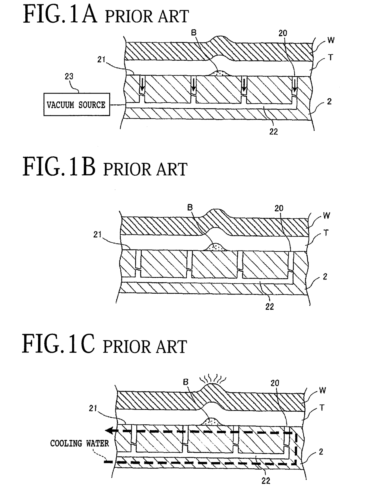
[0015]In a plasma etching apparatus, a wafer processed by grinding is held on an electrostatic chuck by electrostatic attraction. FIGS. 1A, 1B, and 1C are enlarged sectional views of an essential part of a conventional electrostatic chuck 2 in the case that a wafer W is held on the electrostatic chuck 2. FIG. 1A shows a condition that the wafer W has just been loaded into a chamber in a plasma etching apparatus, FIG. 1B shows a condition that the chamber has been evacuated, and FIG. 1C shows a condition that plasma etching is being performed in the chamber.

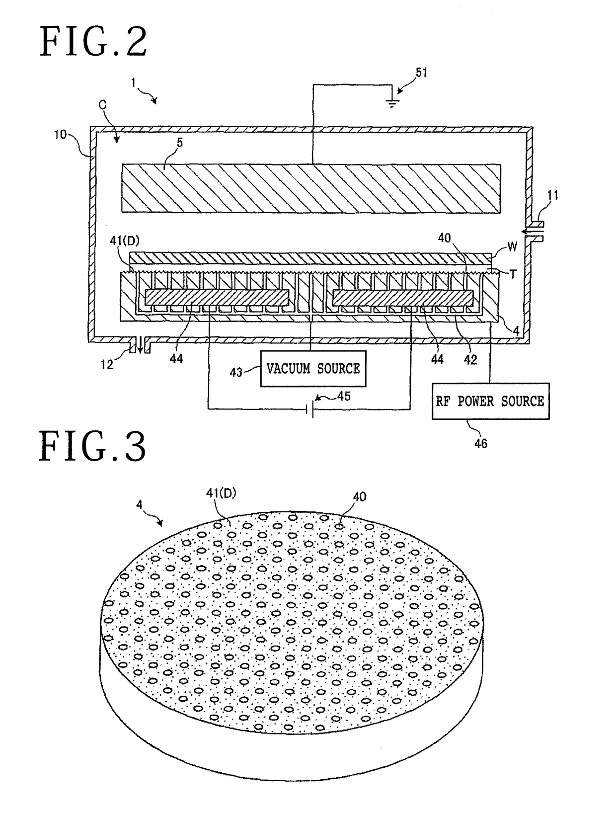
[0016]As shown in FIGS. 1A to 1C, the electrostatic chuck 2 is provided in a chamber C (see FIG. 2) constituting a vacuum chamber. The electrostatic chuck 2 is formed from a disk-shaped member larger in diameter than the wafer W. A plurality of fine holes 20 are formed in the disk-shaped member constituting the electrostatic chuck 2 so as to be exposed to the upper surface of the disk-shaped member, that is, the upper surface of t...


PUM


Abstract

Disclosed herein is an electrostatic chuck having a holding surface for holding a wafer with a tape attached to one side of the wafer in the condition where the tape is in contact with the holding surface. The electrostatic chuck includes a disk-shaped member having a plurality of fine holes communicating with a vacuum source, the fine holes being exposed to the holding surface, a plurality of asperities formed on the holding surface and connected to the fine holes, and an electrode embedded in the disk-shaped member. When the vacuum source is operated to produce a vacuum on the holding surface through the fine holes and thereby hold the wafer through the tape on the holding surface under suction, the asperities formed on the holding surface function as a suction passage communicating with the fine holes.

Description

BACKGROUND OF THE INVENTIONField of the Invention[0001]The present invention relates to an electrostatic chuck.Description of the Related Art[0002]After grinding a wafer by using a grinding apparatus, grinding marks are left on the ground surface (work surface) of the wafer. The grinding marks cause a reduction in die strength of the wafer. To cope with this problem, there has been proposed a plasma etching apparatus for performing plasma etching to thereby remove the grinding marks from the ground surface of the wafer (see Japanese Patent Laid-open No. 2016-143785, for example). In the plasma etching apparatus, the wafer is transferred from the outside of a chamber (vacuum chamber) through a load / unload door into the chamber, and an etching gas is next supplied into the chamber in the condition where the chamber has been evacuated. The etching gas in the chamber is next dissociated into a plasma, which reacts with the wafer to thereby remove the grinding marks from the ground surfa...

Claims


Application Information

Patent Timeline
IPC IPC(8): H01L21/683H01L21/67H01L21/3065
CPCH01L21/6833H01L21/6838H01L21/3065H01L21/67069H01L21/6836H01L21/6831H01L21/6875H01L2221/68327H01L2221/6834H01L21/67132H01L21/67063
Inventor CHITO, KENTAIIDA, HIDEKAZUYAMADA, TOMOHIRONISHIDA, YOSHITERUTAKAHASHI, HIROYUKIFUJIYA, RYOKOYOKOO, SUSUMU
Owner DISCO CORP
Why Eureka
Try Eureka