Internal combustion engine

a combustion engine and combustion chamber technology, applied in the direction of machines/engines, auxiliary lubrication, crankcase compression engine lubrication, etc., to achieve the effect of generating bubbles in the oil

Active Publication Date: 2012-03-20
HONDA MOTOR CO LTD
View PDF17 Cites 1 Cited by
  • Summary
  • Abstract
  • Description
  • Claims
  • Application Information

AI Technical Summary

Benefits of technology

[0014]In the internal combustion engine according to an embodiment of the present invention, in the generator chamber, a shielding rib is provided which is disposed between the generator and the oil introduction port in side view and which extends skewly upwardly from the oil introduction port in the manner of covering one end side of the oil introduction port. A guide rib extends from a side wall of the generator chamber in the manner of covering the other end side of the oil introduction port. Therefore, the oil splashed from the generator is shielded by the shielding rib, and flows down the shielding rib to the oil introduction port. Consequently, oil is prevented from directly entering the oil introduction port of the oil sump chamber, and the generation of bubbles in the oil due to impingement of the splashed oil on the reserved oil can be prevented from occurring. In addition, as for the oil splashed inside the generator chamber, the oil is collected by the guide rib and is guided to the oil introduction port. This also ensures that generation of bubbles in the oil due to impingement of the splashed oil on the reserved oil can be prevented from occurring.
[0015]In addition, a bottom wall of the generator chamber is formed at such an inclination so as to gradually rise from one end side of the oil introduction port, and the shielding rib is provided with a groove for guiding the oil from the bottom wall to the oil introduction port. Therefore, the oil collected at the bottom wall of the generator chamber flows along the inclination to one end side of the shielding rib, and is thereafter guided through the groove to the oil introduction port. Accordingly, the oil can be guided to the oil introduction port while preventing such a strong impingement (collision) that bubbles would mix into the oil.
[0016]Further, the guide rib is disposed so as to be above the shielding rib in the vertical direction and to overlap with the shielding rib in side view, and is formed at such a downward inclination that an end part in the extension direction of the guide rib is located below the center of a crankshaft. Therefore, the oil collected by the guide rib flows down onto the shielding rib, to be farther collected by the shielding rib. Accordingly, oil can be guided to the oil introduction port while obviating such a strong impingement (collision) that bubbles would mix into the oil. In addition, the guide rib receives the oil splashed during the course of the cam chain coming out of engagement with the sprocket provided on the crankshaft. Therefore, the oil can be received by the guide rib in its course of being splashed most. Consequently, the splashed oil can be prevented from impinging on the oil reserved in the oil sump chamber, and generation of bubbles in the oil can be obviated thereby.

Problems solved by technology

According to this configuration, it can be made difficult, by the shielding rib, for the oil splashed from the generator to directly enter the oil introduction port.
In addition, it can be made difficult, by the guide rib, for the oil splashed inside the generator chamber to directly enter the oil introduction port.

Method used


Image

  • Internal combustion engine
  • Internal combustion engine
  • Internal combustion engine

Examples


Embodiment Construction

[0030]Now, an internal combustion engine according to an embodiment of the present invention will be described below referring to the drawings. Reference to upward and downward, forward and rearward, and leftward and rightward directions in the following description refer to the directions as viewed from the driver.

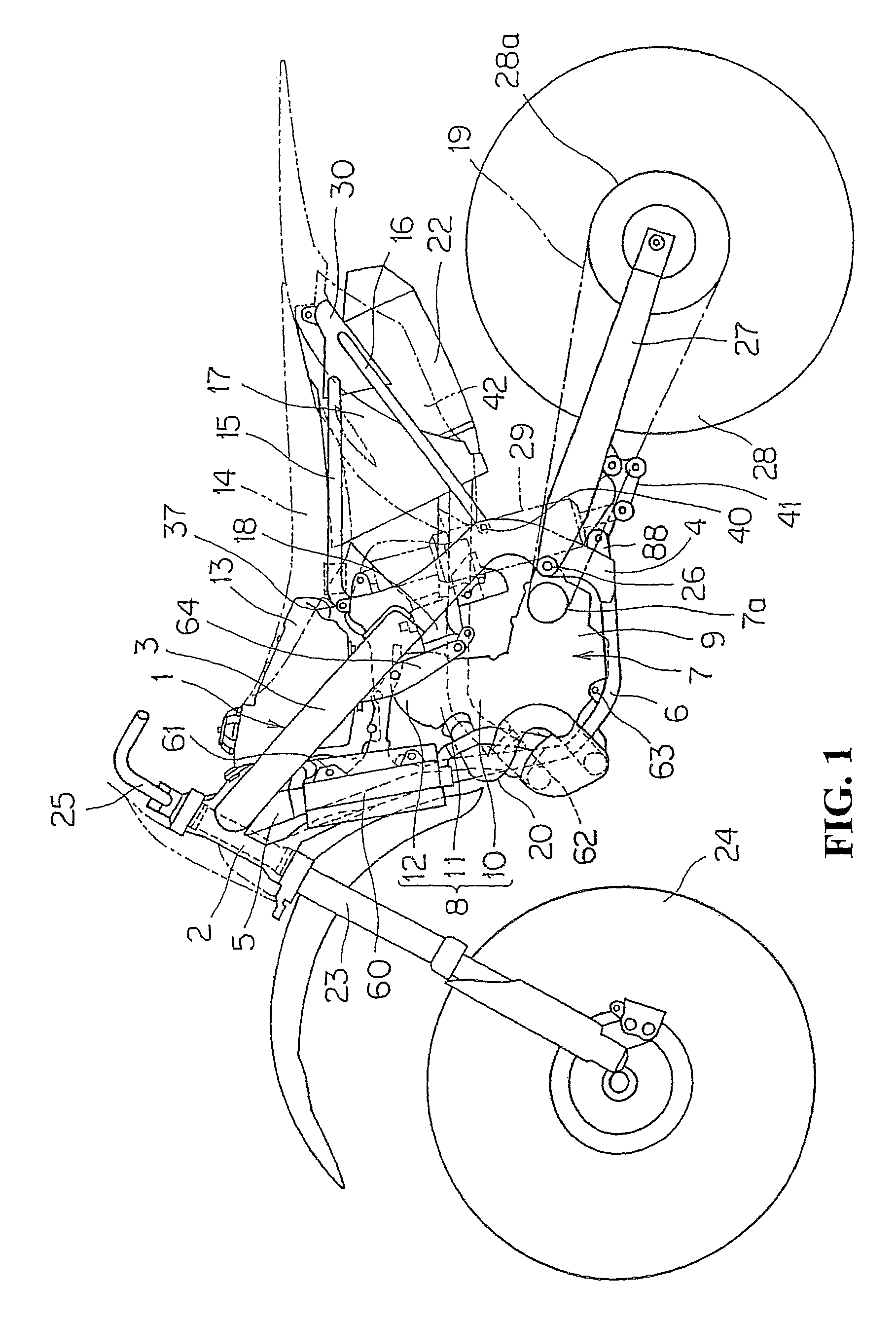
[0031]FIG. 1 is a side view of an offroad motorcycle according to an embodiment of the present invention.

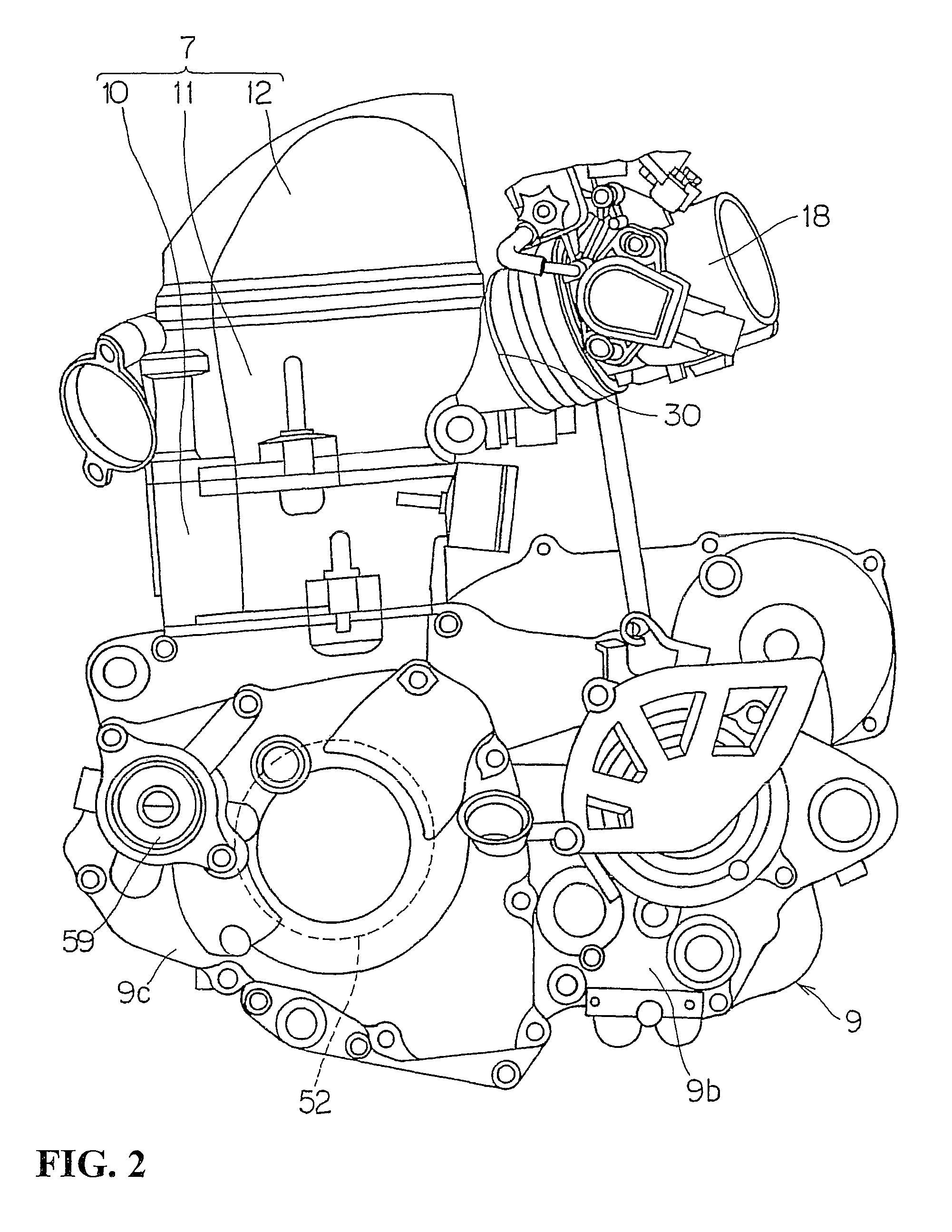
[0032]A body frame 1 of this motorcycle includes a head pipe 2, main frames 3, center frames 4, a down frame 5 and lower frames 6, which are connected to one another in a loop form with an engine 7 supported on the inside thereof. The engine 7 has a cylinder 8 and a crankcase 9. The main frames 3, the center frames 4 and the lower frames 6 are provided in left-right pairs, whereas the head pipe 2 and the down frame 5 are provided as single members along the center of the vehicle body.

[0033]The main frames 3 extend over the engine 7 rectilinearly and downwardly rearward...


PUM


Abstract

An internal combustion engine in which it can be made difficult for bubbles to mix into oil in a flowing-down process of the oil. In a generator chamber, a shielding rib is provided which is disposed between a generator and an oil introduction port in side view and which extends skewly upwardly from the oil introduction port in a manner so as to cover one end side of the oil introduction port. A guide rib extends from a side wall of the generator chamber in the manner of covering the other end side of the oil introduction port.

Description

CROSS-REFERENCE TO RELATED APPLICATIONS[0001]The present application claims priority under 35 USC 119 to Japanese Patent Application No. 2008-197885 filed on Jul. 31, 2008 the entire contents of which are hereby incorporated by reference.BACKGROUND OF THE INVENTION[0002]1. Field of the Invention[0003]The present invention relates to an internal combustion engine having a lubrication structure for circulating oil.[0004]2. Description of Background Art[0005]An internal combustion engine is known wherein a lubrication structure is provided for circulatorily supplying oil to sliding parts. In such an internal combustion engine, a structure has been adopted in which the oil is supplied to the sliding parts (e.g., a generator, a cam chain, etc.) by use of an oil pump. The oil lubricates the sliding parts and flows down into an oil sump chamber provided at a lower part of the crankcase. The oil that flows down into and is reserved in the oil sump chamber is pumped up by the oil pump, and i...

Claims


Application Information

Patent Timeline
Patent Type & Authority Patents(United States)
IPC IPC(8): F01M1/02
CPCF01M11/0004F02F7/0068F01M2011/0033F01M2011/0037F01M2011/005
Inventor OCHIAI, SHUICHITSUBAKINO, YUKIHIRONISHIYAMA, SHINYA
Owner HONDA MOTOR CO LTD
Why Eureka
Try Eureka