
Interlocking, reconfigurable, reconstitutable, reformable cell-based space system

a cell-based space and cell technology, applied in the field of space systems, can solve the problems of large and expensive units that are inoperable, require an even more expensive servicing mission, and other technologies lack the ability to facilitate space system assembly on a “block-by-block” basis. the effect of the cell

Active Publication Date: 2019-01-24
THE AEROSPACE CORPORATION
View PDF9 Cites 14 Cited by
  • Summary
  • Abstract
  • Description
  • Claims
  • Application Information

AI Technical Summary

Benefits of technology

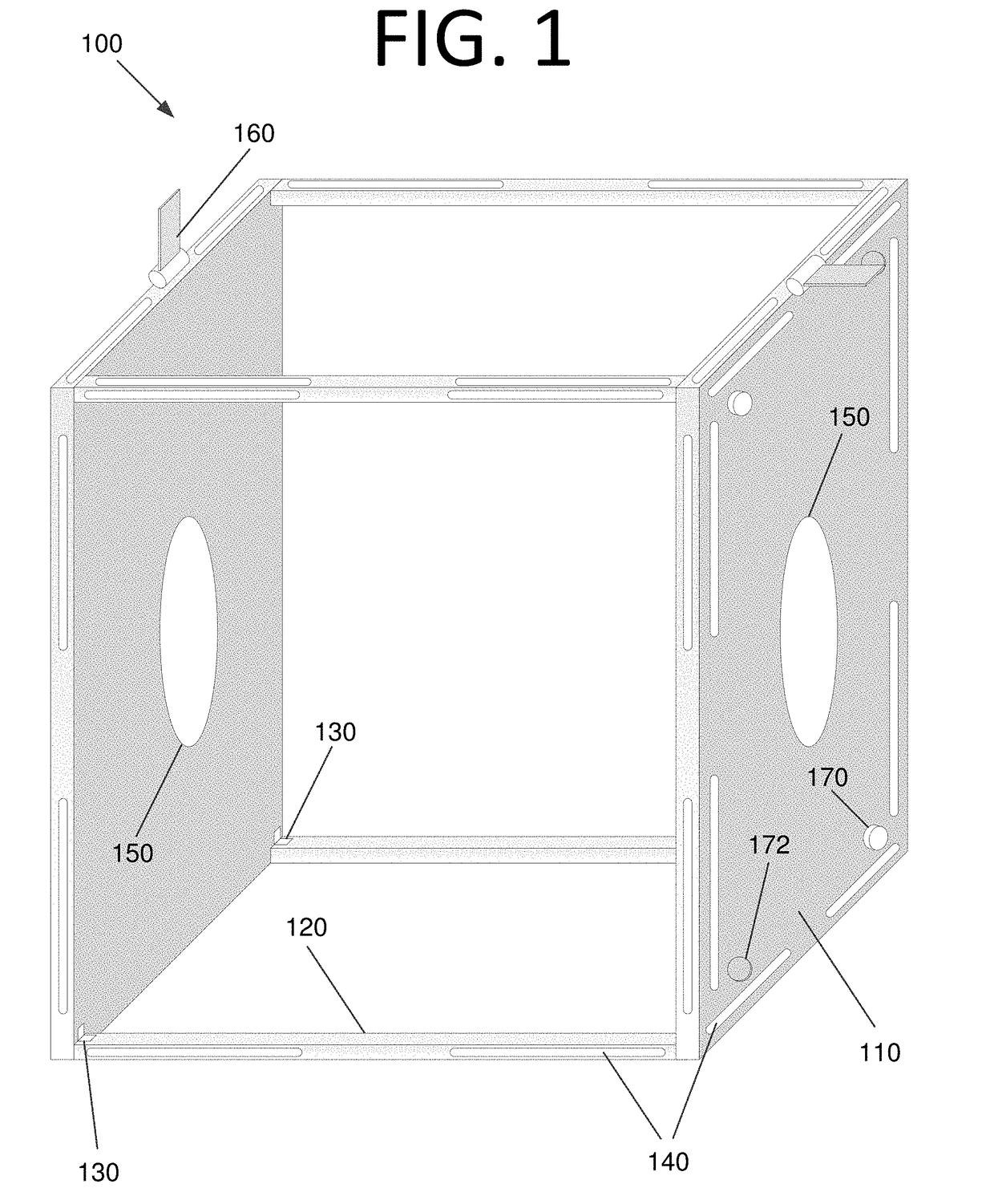
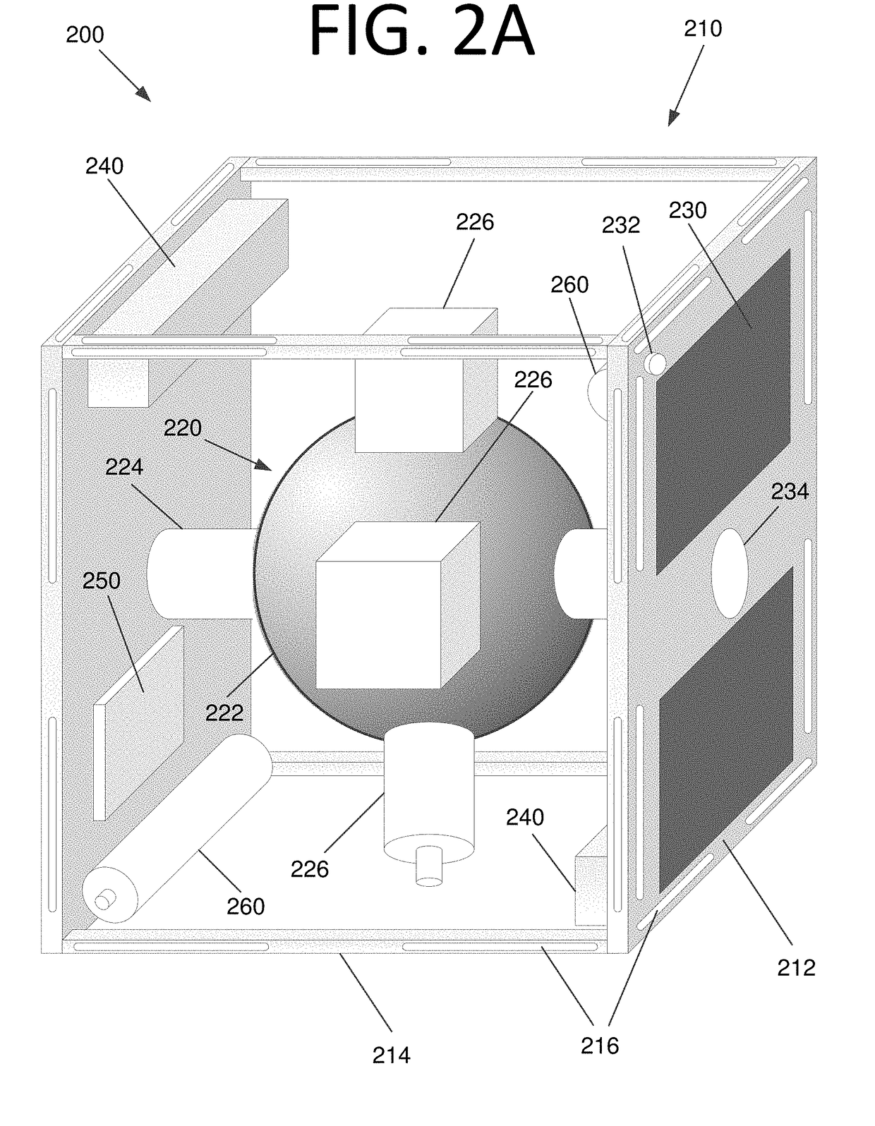
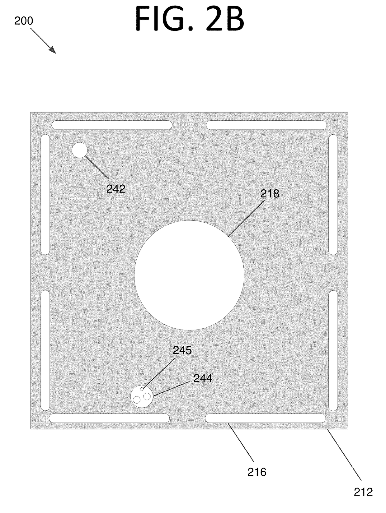
The present invention provides solutions for problems in conventional space systems by providing cell-based space systems that can interlock and reconfigure the ensemble topology, and redirect the orientation of multiple payloads. The cells have a connection mechanism that facilitates connection with other cells, and a plurality of components housed within or connected to the frame, including a camera, sensors, light source, radio frequency antenna, laser telemetry transceiver, transceiver, thermometer, radiation detector, spectrometer, reaction wheels, attitude determination and control system, processing circuitry, solar array, single pixel image counter, photon counter, payload, or any combination thereof. The cells can also include a "flight" computer to control the cells to perform a desired mission. The technical effects of the invention include the ability to change the configuration of the space system quickly and efficiently, and the ability to perform complex missions with multiple payloads.

Problems solved by technology

However, increasing space system size as a monolithic entity has various drawbacks, including: (1) increasing size requires an ever larger and more costly launch vehicle, (2) larger monolithic entities serve as a larger target for nefarious activity; and (3) the failure of a critical subsystem can render the very large and expensive unit inoperative, requiring an even more expensive servicing mission.
While some reconfigurable robotics have been demonstrated for terrestrial applications, there have been no such demonstrations in space.
However, this and other technologies lack the ability to facilitate space system assembly on a “block-by-block” basis, as well as to modify the functionality of individual blocks on the fly, or to remove and replace defective modules.

Method used


Image

  • Interlocking, reconfigurable, reconstitutable, reformable cell-based space system
  • Interlocking, reconfigurable, reconstitutable, reformable cell-based space system
  • Interlocking, reconfigurable, reconstitutable, reformable cell-based space system

Examples


Embodiment Construction

[0034]Some embodiments of the present invention pertain to cell-based space systems that interlock and can change configuration to support a mission. In some embodiments, cells include microelectromechanical system (MEMS) inertial sensors, high torque motors, small reaction wheels, high energy storage batteries, nonlinear control systems, miniature magnetics, direct current (DC) brushless “flat motors,” and microprocessors. Disturbances caused by ensemble or individual cell maneuvers could be mitigated by existing control systems technologies. In cube-shaped cells, in some embodiments, the power cost to introduce a 90° rotation in space may be approximately 25 milliwatts (mW).

[0035]Space systems of a relatively large size may be assembled using individual “cells”, which are individual space vehicles themselves, but also have the capability for individual action within an ensemble of multiple cells. The cells may be held together via magnets or electromagnets in some embodiments. In ...


PUM


Abstract

Cell-based systems may interlock in a reconfigurable configuration to support a mission. Space systems, for example, of a relatively large size may be assembled using an ensemble of individual “cells”, which are individual space vehicles. The cells may be held together via magnets, electromagnets, mechanical interlocks, etc. The topology or shape of the joined cells may be altered by cells hopping, rotating, or “rolling” along the joint ensemble. The cells may be multifunctional, mass producible units. Rotation of cell faces, or of components within cells, may change the functionality of the cell. The cell maybe collapsible for stowage or during launch.

Description

FIELD[0001]The present invention generally pertains to space systems, and more particularly, to cell-based space systems that interlock and reconfigure the ensemble topology, and / or redirect the orientation of multiple payloads.BACKGROUND[0002]In the past 60 years, space systems have matured to the point that they are a strategic necessity for governments and a commercial boon for the communications and entertainment service industries. More industrial applications are expected to follow. Examples of the current success stories are numerous and well documented. Leaving aside the scientific missions, many current and future space applications would be enhanced if the space systems were larger (e.g., more transponders, higher power beams, more aperture, etc.). However, increasing space system size as a monolithic entity has various drawbacks, including: (1) increasing size requires an ever larger and more costly launch vehicle, (2) larger monolithic entities serve as a larger target f...

Claims


Application Information

Patent Timeline
Patent Type & Authority Applications(United States)
IPC IPC(8): B64G1/28B64G1/44G05D1/08B64G1/64
CPCB64G1/283B64G1/443B64G1/645B64G1/646G05D1/0883B64G1/244B64G1/10B64G1/66B64G1/223B64G1/6462B64G1/1085
Inventor HELVAJIAN, HENRYVILLAHERMOSA, RANDY
Owner THE AEROSPACE CORPORATION
Learn More