Optical waveguide

a waveguide and optical wave technology, applied in the field of optical waveguides, to achieve the effect of preventing the attenuation of light propagating in the core, enhancing crosstalk without high costs, and reducing the cost of operation

Active Publication Date: 2019-01-24
NITTO DENKO CORP
View PDF3 Cites 4 Cited by
  • Summary
  • Abstract
  • Description
  • Claims
  • Application Information

AI Technical Summary

Benefits of technology

[0014]In particular, in the case where the non-contacting relationship between the cores and the light absorbing part is established by a cladding surrounding the cores, the suppression of crosstalk is enhanced without high costs because the cladding is typically used in the optical waveguide.
[0015]In particular, in the case where the cladding is made of a resin, the non-contacting relationship between the cores and the light absorbing part is maintained with higher reliability. Thus, the attenuation of light propagating in the cores is prevented with higher reliability.
[0016]Further, in the case where the cladding is covered with the light absorbing part, the area of the light absorbing part is made large adjacent to the light exit member connecting portions disposed in the first end portions of the adjacent cores. This increases the amount of light impinging upon and absorbed by the light absorbing part to further enhance the suppression of crosstalk.
[0017]Also, in the case where the cladding is made of air, a difference in refractive index between the cores and air (air cladding) is greater. This makes light propagating in the cores less prone to leak from the cores, thereby further enhancing the suppression of crosstalk.

Problems solved by technology

Thus, if light not entering the cores 2 but entering the over cladding 3 enters the dummy cores 20, there often arises a problem such that the light is transmitted through the dummy cores 20.

Method used


Image

  • Optical waveguide
  • Optical waveguide
  • Optical waveguide

Examples


##ventive example 1

Inventive Example 1

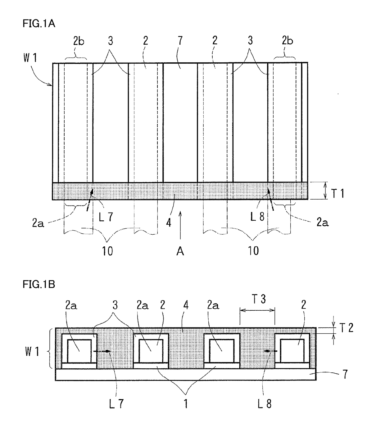
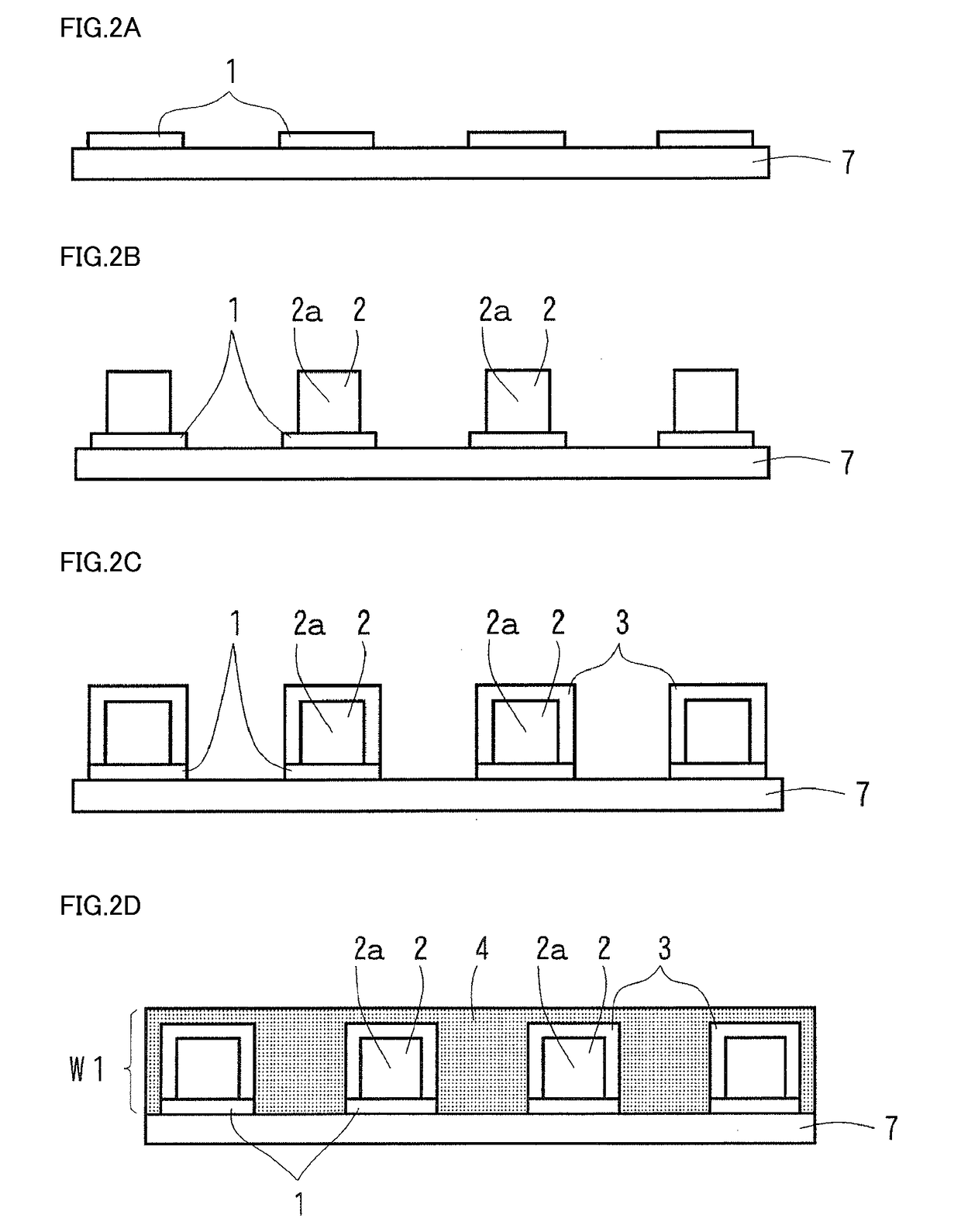
[0109]Using the aforementioned materials, the optical waveguide (having a length of 50 mm) of the first embodiment shown in FIGS. 1A and 1B was produced on a surface of a substrate made of a resin. The under claddings had the following dimensions: a thickness of 40 μm; a width of 100 μm; and a gap width of 150 μm between adjacent ones of the under claddings. The cores had the following dimensions: a thickness of 40 μm; a width of 40 μm; and a spacing of 250 μm therebetween. Portions of the over claddings which covered the side surfaces of the cores had a thickness of 30 μm, and portions of the over claddings which covered the top surfaces of the cores had a thickness of 30 μm. The light absorbing part had the following dimensions: a depth of 10 mm as measured from a first end surface of the optical waveguide; a width of 150 μm in portions present between adjacent ones of the over claddings; and a thickness of 15 μm as measured from the top surfaces of the over cla...

##ventive example 2

Inventive Example 2

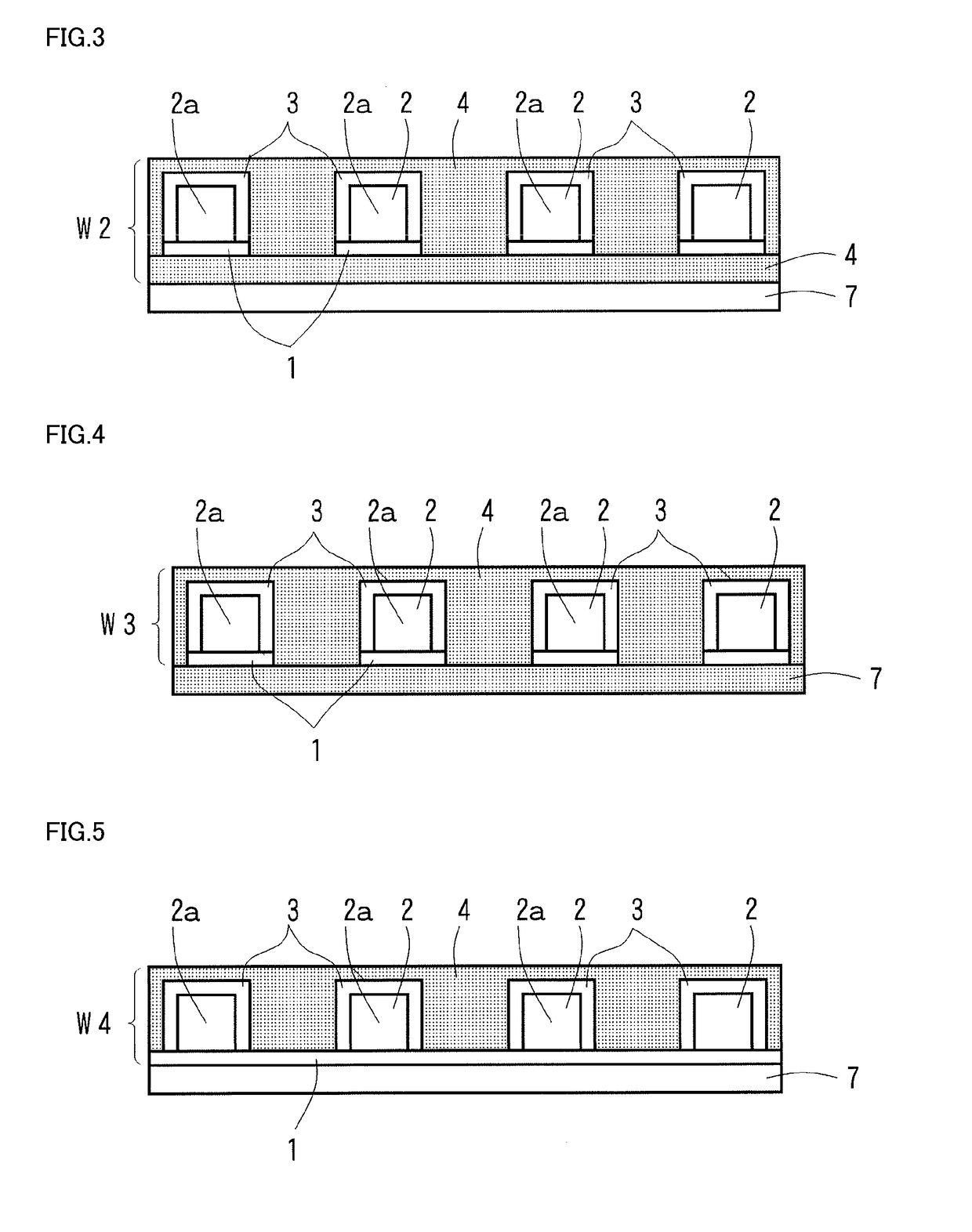
[0110]Using the aforementioned materials, the optical waveguide (having a length of 50 mm) of the second embodiment shown in FIG. 3 was produced on a surface of a substrate made of a resin. The layer of the light absorbing part provided between the under claddings and the substrate had a thickness of 20 μm. The remaining parts had the same dimensions as those in Inventive Example 1.

##ventive example 3

Inventive Example 3

[0111]Using the aforementioned materials, the optical waveguide (having a length of 50 mm) of the fourth embodiment shown in FIG. 5 was produced on a surface of a substrate made of a resin. The components including the cores had the same dimensions as those in Inventive Example 1.


PUM


Abstract

The present disclosure provides an optical waveguide capable of enhancing the suppression of crosstalk. This optical waveguide includes: under claddings; cores for light propagation arranged in side-by-side relation on surfaces of the respective under claddings; over claddings covering the cores; and a light absorbing part provided between adjacent ones of the cores and adjacent to light exit member connecting portions for connection to light exit members, the light exit member connecting portions being disposed in first end portions of the adjacent cores, the light absorbing part being in non-contacting relationship with the cores. The light absorbing part contains a light absorbing agent having an ability to absorb light exiting the light exit members. The optical waveguide is produced on a surface of a substrate.

Description

TECHNICAL FIELD[0001]The present disclosure relates to an optical waveguide for use in the fields of optical communications, optical information processing and other general optics.BACKGROUND ART[0002]As shown in FIG. 16A in plan view and as shown in FIG. 16B in sectional view taken along the line D-D of FIG. 16A, an optical waveguide W19 in general includes: an under cladding 1; linear cores 2 for light propagation protruding in a predetermined pattern and formed on a surface of the under cladding 1; and an over cladding 3 formed on the surface of the under cladding 1 so as to cover the cores 2. The optical waveguide W19 is configured such that light enters a light entrance portion 2a disposed in a first end portion of each of the cores 2 and that the light exits alight exit portion 2b disposed in a second end portion of each of the cores 2. Specifically, a light exit member 10 such as an optical fiber, a light-emitting element, or the like is connected to the light entrance portio...

Claims


Application Information

Patent Timeline
Patent Type & Authority Applications(United States)
IPC IPC(8): G02B6/122G02B6/02G02B26/08
CPCG02B6/122G02B6/02033G02B26/0816G02B2006/12126G02B6/1221G02B6/138G02B2006/12176G02B6/43G02B6/4214G02B6/425G02B6/00
Inventor TSUJITA, YUICHIOKAMOTO, NORIHIKO
Owner NITTO DENKO CORP
Why Eureka
Try Eureka