Fuse element

a fuse element and element technology, applied in the direction of printed circuit aspects, heating/cooling contact switches, electrical equipment, etc., can solve the problems of unable to ensure cannot define with certainty the remaining elastic force, and cannot guarantee whether the electrical circuit is interrupted, so as to achieve reliable fastening of the fuse element, sufficient elastic force, and simple assembly

Active Publication Date: 2019-01-24
BASS WOLFGANG
View PDF7 Cites 0 Cited by
  • Summary
  • Abstract
  • Description
  • Claims
  • Application Information

AI Technical Summary

Benefits of technology

[0016]As compared to this, the object underlying the present invention is to configure a fuse element of the type described in the beginning such that, on the one hand, simplified assembly with reliable fastening of the fuse element is guaranteed and, on the other hand, sufficient elastic force can be exactly adjusted even for a rather long useful life.
[0018]It is achieved by the structure and the functioning of the fuse element according to the invention that with the presence of the trigger criterion in combination with an excess temperature or over-temperature the fuse element adapted to be arranged on a circuit board is reliably triggered for interrupting a defined electric circuit. Thus, when a soldered area is fused in the surface area of the fuse element due to the excess temperature (irrespective of the source of heat), then the predetermined elastic force acting on the surface area can lift the latter off the soldering area and, resp., the soldering points and thus from the bridged conductor paths so that safe disconnection of the electric circuit is ensured after the trigger condition is given.
[0019]After completing the fuse element in the original and not elastically deformed configuration, no further plastic deformations are required any more. Rather, by means of simple manufacturing operations the finished fuse element can be soldered onto the conductor paths (and thus on one side), and for providing the required elastic force on the surface area by means of low pressure onto the central area of the fuse element the hook-shaped element can be achieved to safely and positively engage in the opening of the circuit board. Plastic deformations are neither required any more nor are they desired, and all of the deformations to be carried out after completion are carried out exclusively in the elastic area so that an undesired and detrimental change of the characteristics of the fuse element by inadvertent plastic deformation can be exactly dimensioned with respect to the elastic force to be exerted upon the surface area and is not falsified by possible plastic deformations with significant tolerances.
[0020]The elastic force exerted upon the surface area after mounting the fuse element according to the present invention is generated by the entire structure of the fuse element but primarily by the first and second deforming areas in that the elastic deformation can be specifically brought about without any transition to a plastic deformation by low pressure from outside onto the central area for mounting the fuse element on the circuit board. At the same time, the hook-shaped element is caused to engage in the opening within the circuit board which is located adjacent to the contact area. After engagement of the hook-shaped element, at this point a positive connection of the fuse element to the circuit board is given. When the surface area of the fuse element is lifted off due to the elastic force when the function of the fuse element is exerted upon reaching the trigger criterion, then the fuse element continues being connected and fastened to the circuit board due to the positive connection of the collar-shaped element, while the connection between the conductor paths is disconnected safely, efficiently and non-reversibly.
[0021]The arrangement according to the invention thus, on the one hand, guarantees the desired easy manufacture of the fuse element in the complete, undeformed or non-deformed and original state as well as subsequent simple mounting without any further plastic deformations being required, and moreover guarantees safe functioning with a defined or predeterminable elastic force on the surface area as well as an approximately constant force transmission during longer useful life or service life, as the deformations occurring after manufacture and during mounting on the circuit board are located merely within the elastic area. Thus, the fuse element according to the invention allows to achieve reliable triggering when the trigger criterion or criteria is / are present.

Problems solved by technology

By the great current heat occurring due to the excessive current and / or with excessive head supplied from outside the material of the conductor element fuses at a particular point thus causing the electric circuit to be interrupted.
Furthermore, it cannot be ensured whether after plastic deformation in the mounted state the residual elastic deformability and thus the remaining elastic force is safely sufficient to safely disconnect the electric circuit in the case of excess temperature and in the presence of the trigger criterion.
In this context it is difficult, on the one hand, to define with certainty a remaining elastic force in connection with the plastic deformation and to realize the same with the component part and, on the other hand, to ensure a constant elastic force of predetermined strength over a quite long service life.

Method used


Image

  • Fuse element
  • Fuse element
  • Fuse element

Examples


example embodiment

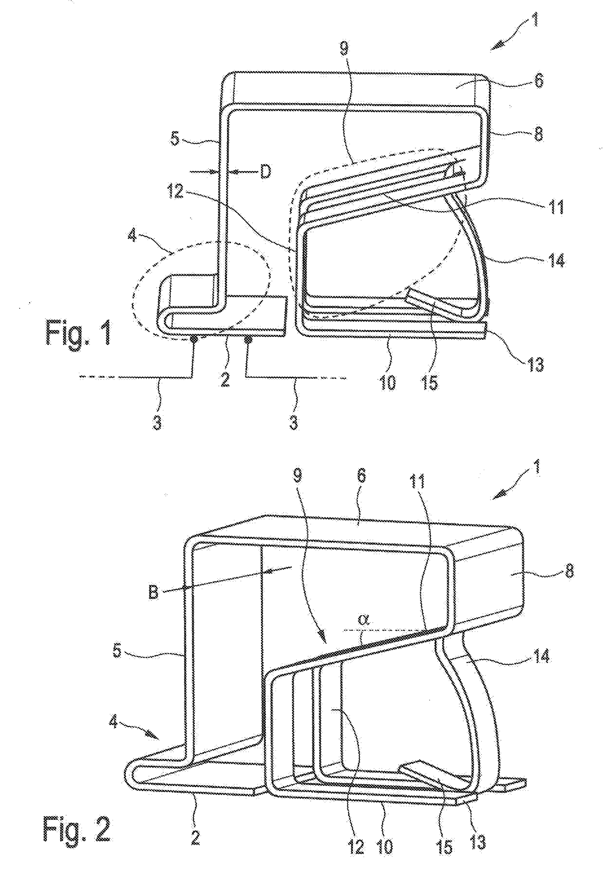
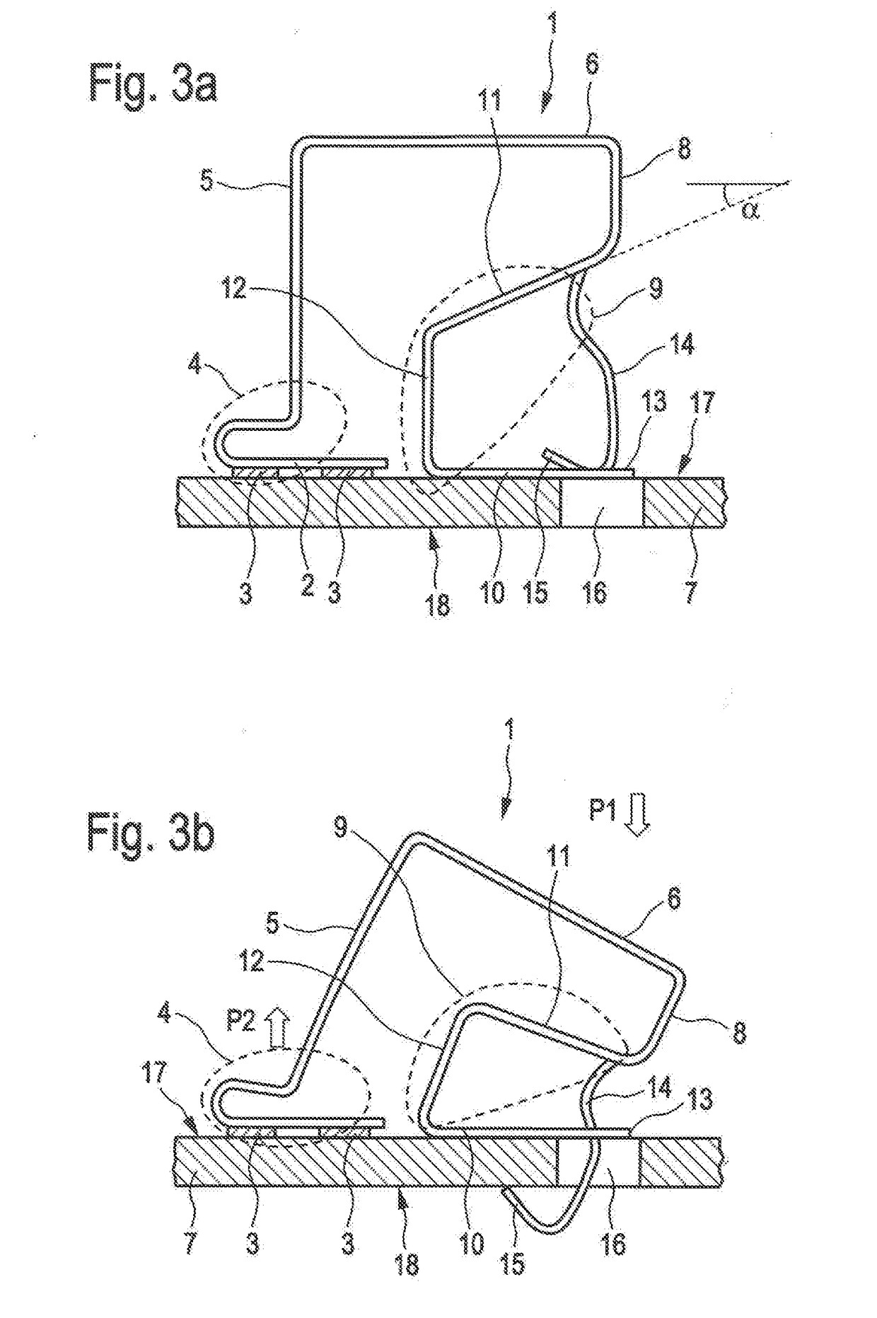
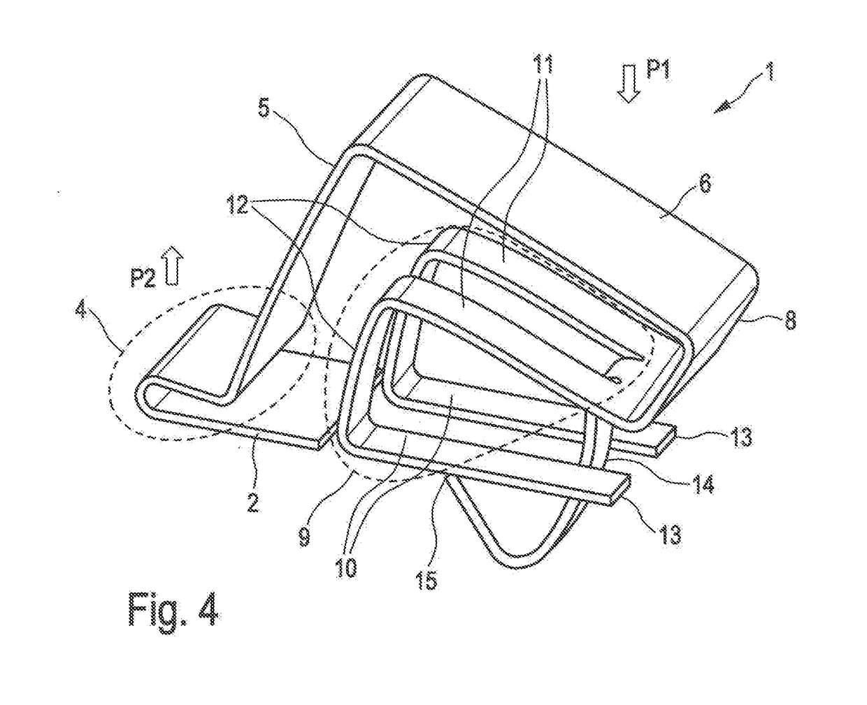
[0042]The basic structure of the fuse element according to the present invention shall be described hereinafter in connection with the representations in FIGS. 1 and 2 by way of an example embodiment. The further FIGS. 3a, 3b and 4 illustrate the arrangement of the fuse element prior to and after mounting on a circuit board 7 according to a deformed and thus operative state. The fuse element 1 thus can be disposed on the circuit board 7.

[0043]According to the representation in FIGS. 1 and 2, preferably the fuse element 1 is formed integrally of a strip of a metallic and especially a solderable material. The material offers the possibility of plastic deformation and further also has sufficient elasticity. The fuse element 1 in the form shown in FIGS. 1 and 2 can be manufactured to the full extent and thus completely by means of appropriate machines. The shape of the fuse element 1 shown in FIGS. 1 and 2 is the shape achieved after complete manufacture or pre-fabrication and, resp., o...


PUM


Abstract

A fuse element for an electric circuit, arranged on a circuit board of the electric circuit, has a surface area for fastening and establishing an electric contact on the circuit board, a first deforming area adjacent the surface area, a second deforming area connected to the first deforming area via a central area, the second deforming area including a contact area that abuts the circuit board, and a hook-shaped element insertable into an opening adjacent the contact area, the hook-shaped element is insertable into the opening by elastic deformation of the fuse element in the direction of the circuit board and, after insertion of the hook-shaped element into the opening and positive holding of the hook-shaped element on a lower surface of the circuit board, the first and second deforming areas exert an elastic force on the surface area in the direction away from the circuit board.

Description

CROSS REFERENCE TO RELATED APPLICATION[0001]This application claims priority under 35 USC § 119 to German Patent Application No. 202017104268.5 filed on Jul. 18, 2017, which application is hereby incorporated by reference in its entirety.TECHNICAL FIELD[0002]The present invention relates to a fuse element for an electric circuit, and especially to a fuse element for protecting the electric circuit by release in the case of excess temperature, the fuse element being adapted to be disposed on a circuit board of the electric circuit.BACKGROUND OF THE INVENTION[0003]In general, electric fuse elements are used in electric and / or electronic circuits in various configurations for the protection of the circuitry against overcurrent and / or especially against inadmissible heating. When the respective trigger conditions occur in connection with overcurrent or excess temperature, the fuse element is triggered and a particular electric circuit within a system and specifically within the circuit ...

Claims


Application Information

Patent Timeline
Patent Type & Authority Applications(United States)
IPC IPC(8): H01H37/76H05K1/02H05K3/34
CPCH01H37/761H05K1/0201H05K1/0263H05K3/341H01H2037/762H01H2037/046H05K2201/10181H05K2201/0311H05K2201/10265H01H2037/763
Inventor BASS, WOLFGANG
Owner BASS WOLFGANG
Why Eureka
Try Eureka