Optical image capturing system
a technology of optical image and capturing system, which is applied in the field of can solve the problems of occupying a significant amount of space occupied by the image elements, affecting the design and manufacture of miniaturized surveillance cameras in the future, and being expensive, so as to shorten the back focal length of the optical image capturing system, effectively reducing the incident angle of the off-axis rays, and correcting the off-axis aberration
- Summary
- Abstract
- Description
- Claims
- Application Information
AI Technical Summary
Benefits of technology
Problems solved by technology
Method used
Image

Examples
first embodiment
The First Embodiment
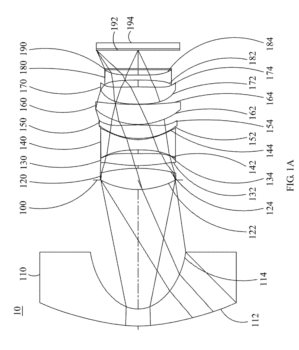
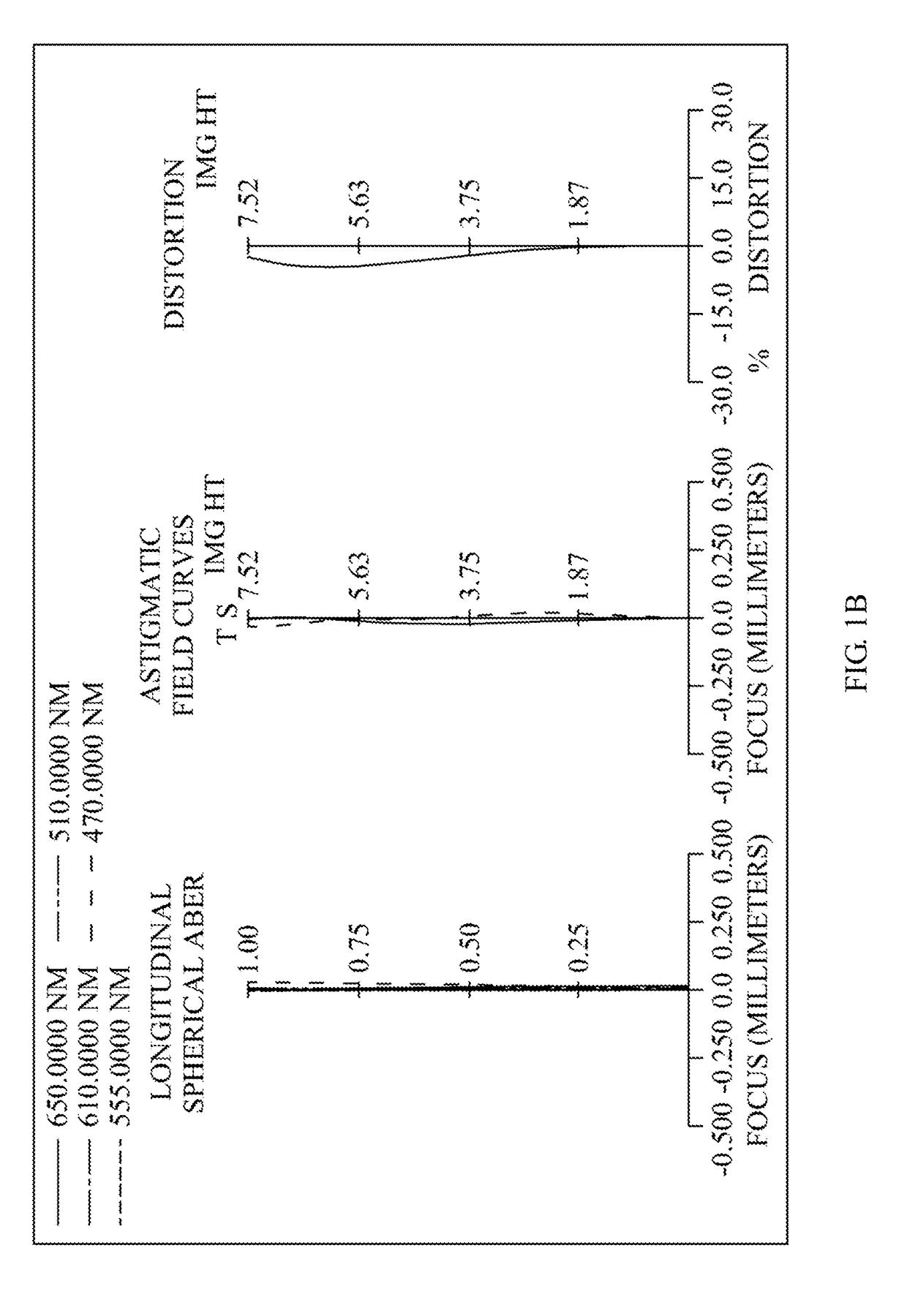
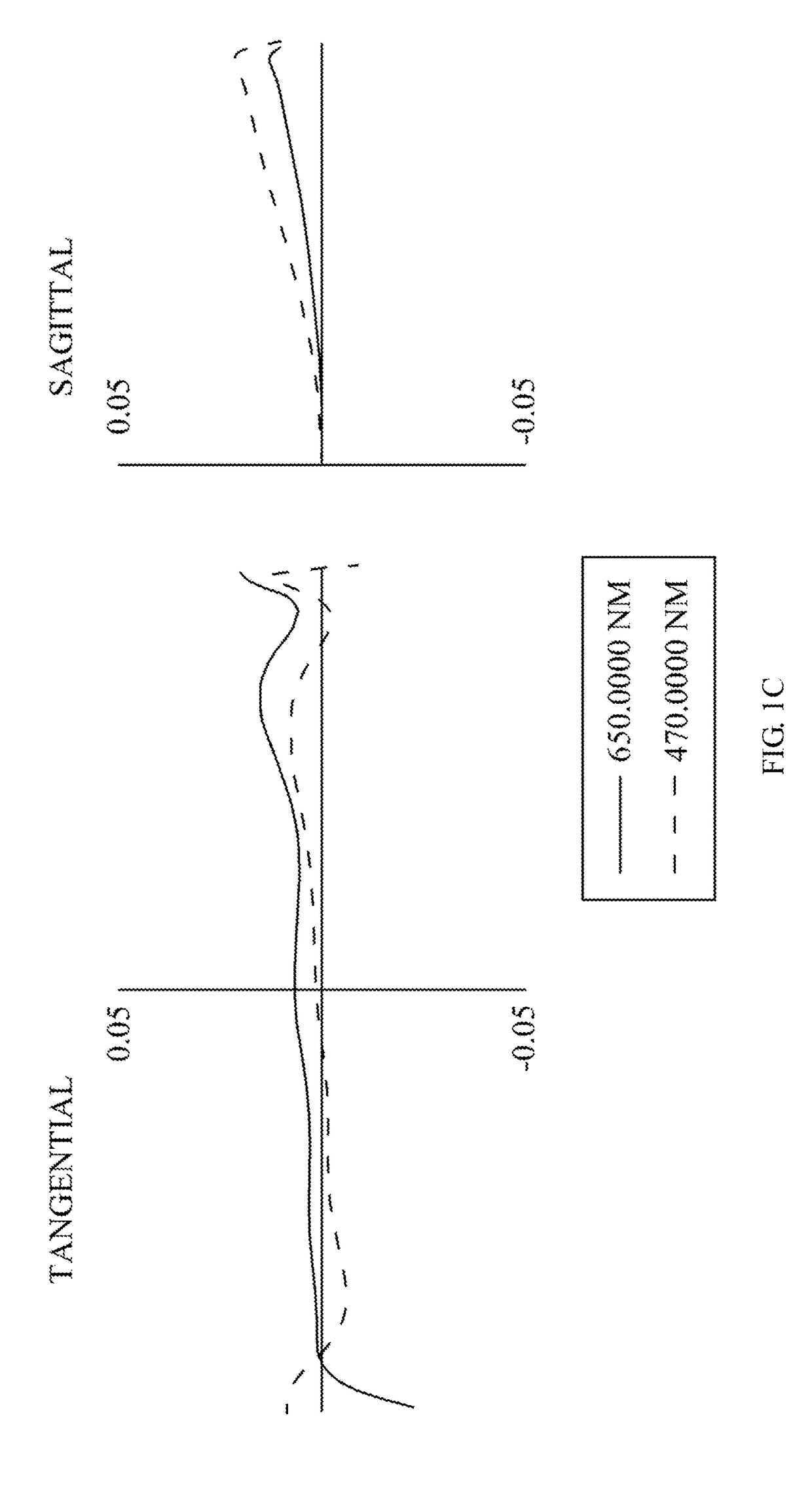
[0108]Please refer to FIG. 1A and FIG. 1B, wherein FIG. 1A is a schematic view of the optical image capturing system according to the first embodiment of the present invention and FIG. 1B shows the longitudinal spherical aberration curves, astigmatic field curves, and optical distortion curve of the optical image capturing system in the order from left to right according to the first embodiment of the present invention. FIG. 1C is a transverse aberration diagram of the longest operation wavelength and the shortest operation wavelength for tangential fan and sagittal fan, of which the longest operation wavelength and the shortest operation wavelength pass through an edge of aperture at the position of 0.7 field of view on the first image plane, according to the first embodiment of the present disclosure. FIG. 1D is a diagram illustrating the through focus MTF values for the visible light spectrum at the central field of view, 0.3 field of view and 0.7 field of vie...
second embodiment
[0166]Please refer to FIG. 2A and FIG. 2B, wherein FIG. 2A is a schematic view of the optical image capturing system according to the second embodiment of the present invention and FIG. 2B shows the longitudinal spherical aberration curves, astigmatic field curves, and optical distortion curve of the optical image capturing system in the order from left to right according to the second embodiment of the present invention. FIG. 2C is a transverse aberration diagram of the longest operation wavelength and the shortest operation wavelength for tangential fan and sagittal fan, of which the longest operation wavelength and the shortest operation wavelength pass through an edge of aperture at the position of 0.7 field of view on the first image plane, according to the second embodiment of the present disclosure. FIG. 2D is a diagram illustrating the through focus MTF values for the visible light spectrum at the central field of view, 0.3 field of view and 0.7 field of view according to th...
third embodiment
[0182]Please refer to FIG. 3A and FIG. 3B, wherein FIG. 3A is a schematic view of the optical image capturing system according to the third embodiment of the present invention and FIG. 3B shows the longitudinal spherical aberration curves, astigmatic field curves, and optical distortion curve of the optical image capturing system in the order from left to right according to the third embodiment of the present invention. FIG. 3C is a transverse aberration diagram of the longest operation wavelength and the shortest operation wavelength for tangential fan and sagittal fan, of which the longest operation wavelength and the shortest operation wavelength pass through an edge of aperture at the position of 0.7 field of view on the first image plane, according to the third embodiment of the present disclosure. FIG. 3D is a diagram illustrating the through focus MTF values for the visible light spectrum at the central field of view, 0.3 field of view and 0.7 field of view according to the f...
PUM
 Abstract
Description
Claims
Application Information
 - R&D
- Intellectual Property
- Life Sciences
- Materials
- Tech Scout
- Unparalleled Data Quality
- Higher Quality Content
- 60% Fewer Hallucinations
Browse by: Latest US Patents, China's latest patents, Technical Efficacy Thesaurus, Application Domain, Technology Topic, Popular Technical Reports.
© 2025 PatSnap. All rights reserved.Legal|Privacy policy|Modern Slavery Act Transparency Statement|Sitemap|About US| Contact US: help@patsnap.com