Eureka AIR delivers breakthrough ideas for toughest innovation challenges, trusted by R&D personnel around the world.

Honing machine with multiple workstations

a workstation and honing machine technology, applied in the field of honing machines, can solve the problems of engine noise, complex functions, and influence on emission values

Inactive Publication Date: 2019-02-07
NAGEL MASCHEN UND WERKZEUGFAB
View PDF0 Cites 2 Cited by
  • Summary
  • Abstract
  • Description
  • Claims
  • Application Information

AI Technical Summary

Benefits of technology

This patent describes an improved design for a honing machine that allows for greater flexibility and efficiency in the processing procedure. The machine includes multiple functional units that can be used in conjunction with each other, including a vertical honing unit and a measuring unit for checking the processing success. The attachment of the vertical honing unit to the machine upper part provides better access for the operator. Additionally, a tool change device can be used for tool changes between the honing station and a tool magazine. These features allow for quicker and easier processing with the same machine, reducing downtime and improving overall efficiency.

Problems solved by technology

The relatively tight tolerances of the decisive parts of an internal combustion engine and of a cylinder crank casing result from the complex functions of these parts.
This has effects on the power, and as a result of the combustion profile also influences the emission values and the engine noise.

Method used


Image

  • Honing machine with multiple workstations
  • Honing machine with multiple workstations
  • Honing machine with multiple workstations

Examples


Embodiment Construction

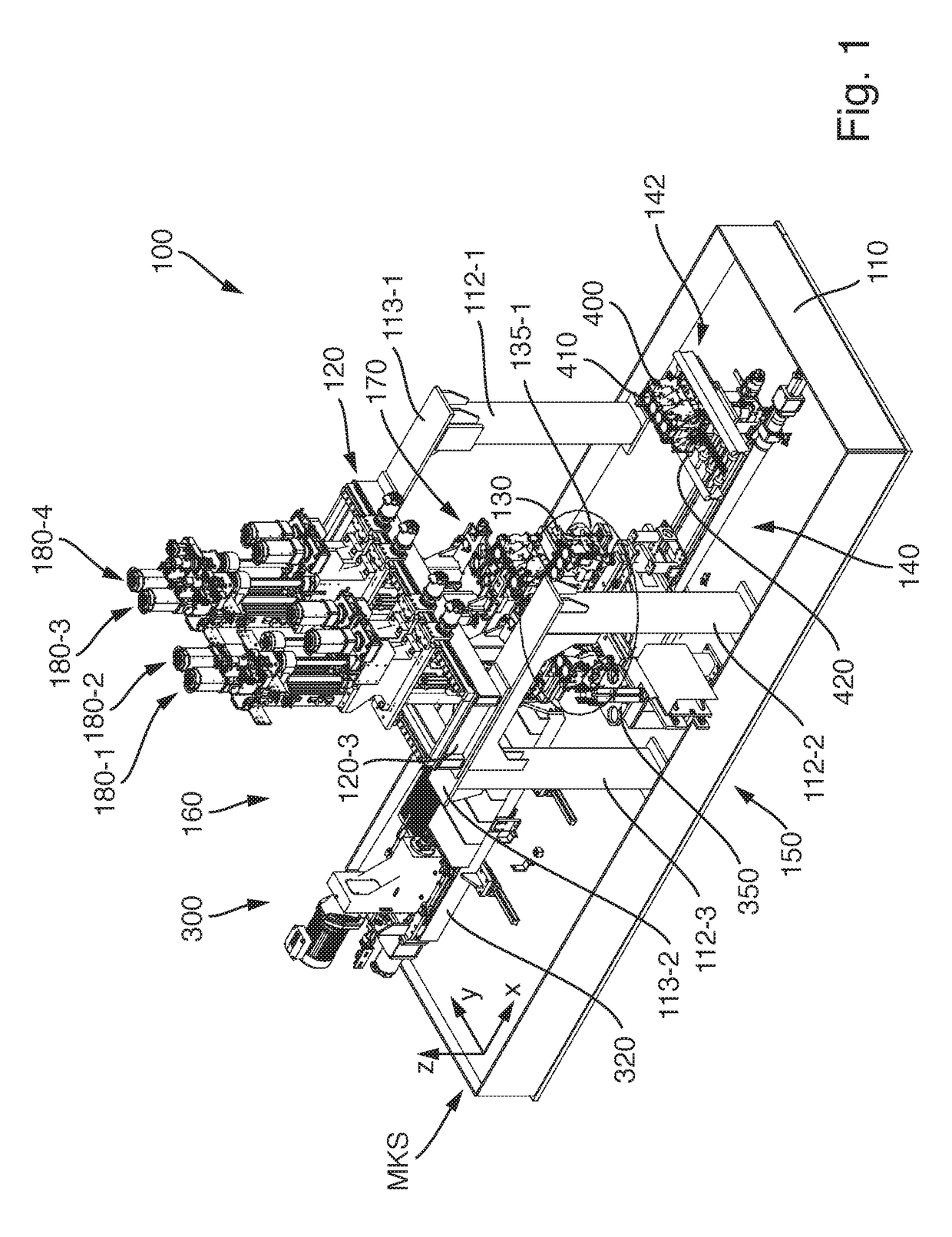
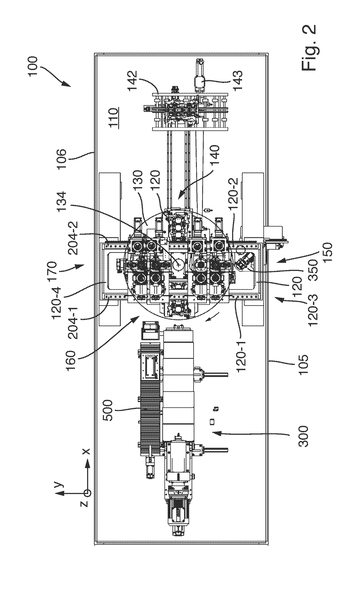
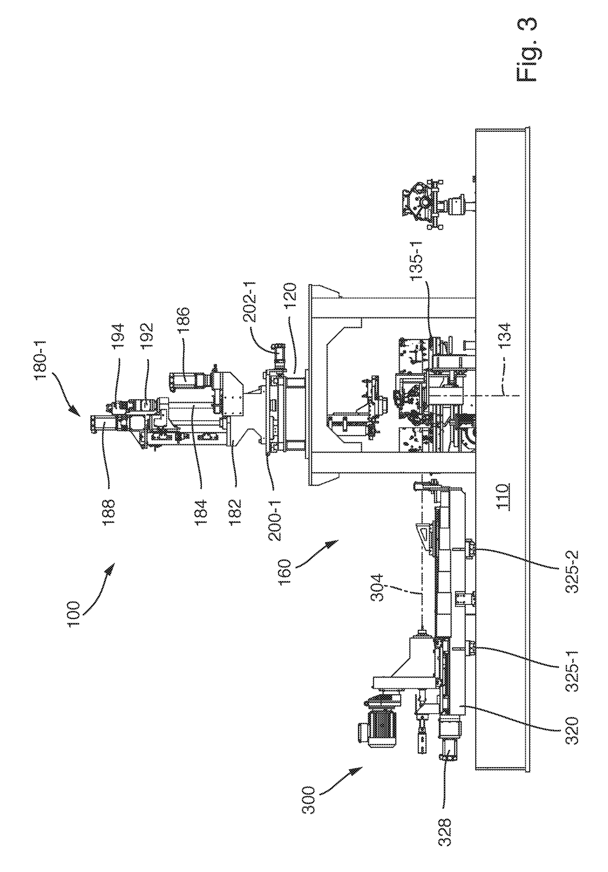
[0037]FIG. 1 shows an oblique perspective view of a honing machine 100 according to an exemplary embodiment of the invention. FIG. 2 shows a plan view of the honing machine. FIG. 3 shows a side view of the longitudinal side and FIG. 4 shows a front view of that side on which the loading and unloading of the honing machine takes place. The honing machine 100 is configured to carry out honing operations, at workpieces with boreholes which are oriented orthogonally with respect to one another, on boreholes with different orientations. In the exemplary case, the honing machine is configured to process, by means of honing, both the cylinder boreholes 410 and the bearing gate borehole 420 (crankshaft borehole), oriented perpendicularly with respect to the cylinder boreholes, on workpieces 400 in the form of cylinder crank casings (engine blocks).

[0038]The honing machine 100 has a machine base 110 which is rectangular in plan view and which bears all the mechanical components of the honing...


PUM

PropertyMeasurementUnit
widthaaaaaaaaaa
widthaaaaaaaaaa
lengthaaaaaaaaaa

Abstract

A honing machine (100) for carrying out honing operations on boreholes, oriented orthogonally with respect to one another, in a workpiece (102), in particular for honing processing of cylinder boreholes and a bearing gate borehole in a cylinder crank casing, comprises a machine base (110) and a round table (130) which is arranged on the machine base and which can rotate about a vertical round table axis (134) and has a plurality of workpiece receptacles which are arranged offset with respect to one another in a circumferential direction at a radial distance from the round table axis, in such a way that a workpiece which is held in a workpiece receptacle can be transported successively to different workstations (140, 150, 160, 170) of the honing machine by rotating the round table. At least one of the workstations is a vertical honing station (150, 170) which has at least one vertical honing unit (180) which has a honing spindle which can move back and forth in the direction of a spindle axis which is oriented parallel to the round table axis, rotatably about said spindle axis. Furthermore, at least one of the workstations is a horizontal honing station (160) which has at least one horizontal honing unit (300) which has a honing spindle which can move back and forth in the direction of a horizontal spindle axis (304), rotatable about said spindle axis. The horizontal honing unit (300) is or can be positioned with respect to the round table (130) in such a way that the horizontal honing unit assumes a processing position in which the horizontal spindle axis (304) is oriented radially with respect to the round table axis (134).

Description

FIELD OF APPLICATION AND PRIOR ART[0001]The invention relates to a honing machine for carrying out honing operations on boreholes oriented orthogonally with respect to one another in a workpiece, in particular for honing processing of cylinder boreholes and a bearing gate borehole in a cylinder crank casing.[0002]The cylinder case casing (ZKG), which is often referred to simply as a “crank casing” or “engine block” is an integral component of internal combustion engines or combustion engines such as are used, for example, in passenger cars or trucks, aircraft, ships or stationary installations. The most widespread design is multi-cylinder engines whose pistons are connected by means of connecting rods to the rotating crankshaft, which passes on the force generated by the engine to wheels, ship's screws, propellers, generators or the like.[0003]The cylinder crank casing is an example of a workpiece with boreholes which are oriented orthogonally with respect to one another.[0004]Withi...

Claims


Application Information

Patent Timeline
Patent Type & Authority Applications(United States)
IPC IPC(8): B24B33/02B24B33/10B24B33/08B24B27/00
CPCB24B33/022B24B33/105B24B33/08B24B27/0023B23H9/08B24B33/02
Inventor NAGEL, BERND
Owner NAGEL MASCHEN UND WERKZEUGFAB
Why Eureka
Eureka Blog
Learn More