Vehicle charging system, parking lot system, and vehicle charging method

Inactive Publication Date: 2019-02-07
NEC CORP
View PDF0 Cites 1 Cited by
  • Summary
  • Abstract
  • Description
  • Claims
  • Application Information

AI Technical Summary

Benefits of technology

The invention aims to improve the convenience of charging multiple vehicles using a non-contact charging apparatus. It provides a vehicle charging system, a parking lot system, and a vehicle charging method that contribute to this improvement. The technical effects of the invention are focused on enhancing the user experience of non-contact charging, making it more accessible and convenient for a larger range of drivers.

Problems solved by technology

However, the user needs to get out of his / her vehicle, to prove to a charging apparatus that the user has the right to receive a charging service, and this is considered as a problem.
Thus, the content in PTL 4 cannot directly be applied, which is considered as a problem.

Method used


Image

  • Vehicle charging system, parking lot system, and vehicle charging method
  • Vehicle charging system, parking lot system, and vehicle charging method
  • Vehicle charging system, parking lot system, and vehicle charging method

Examples


first exemplary embodiment

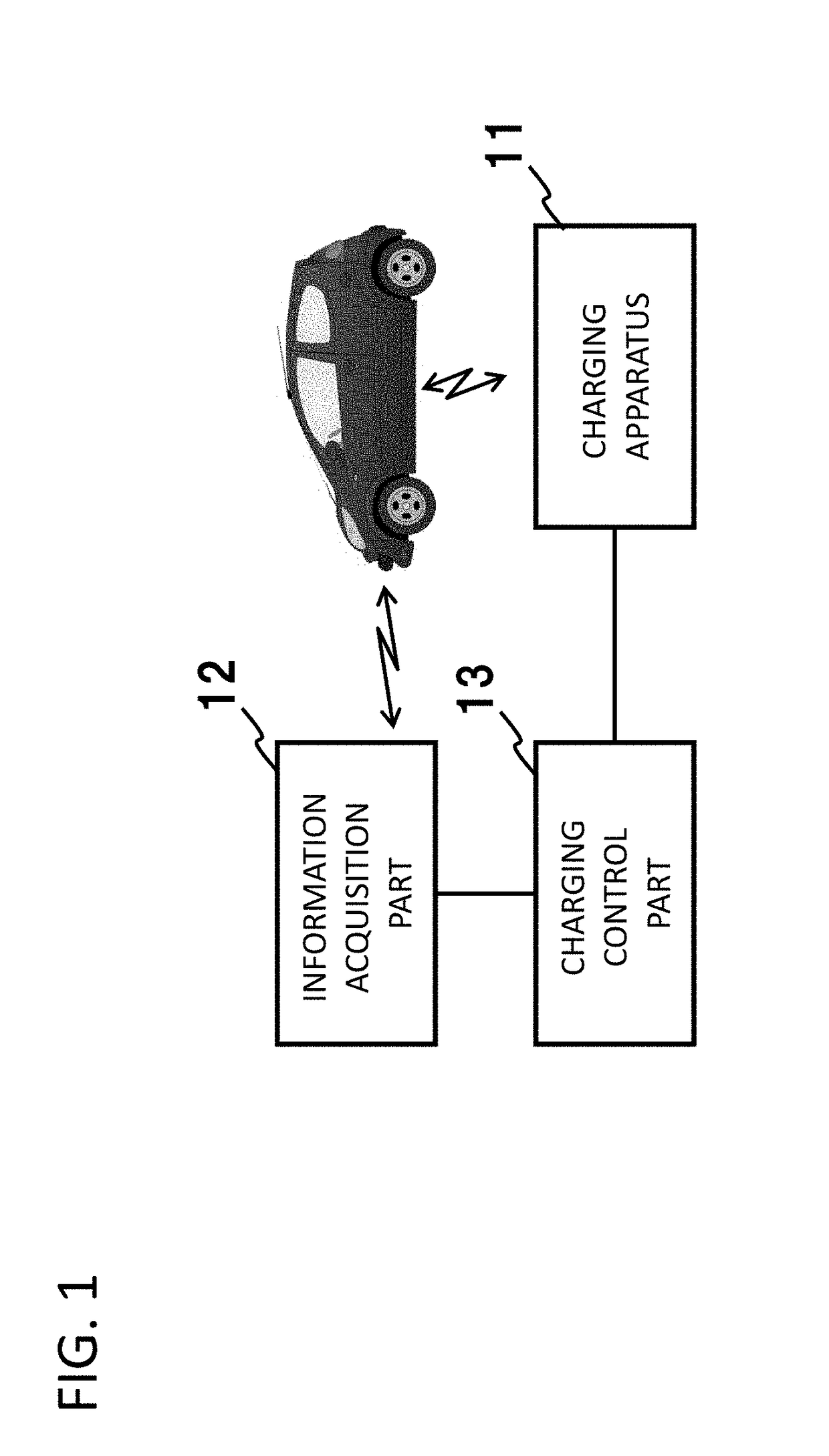
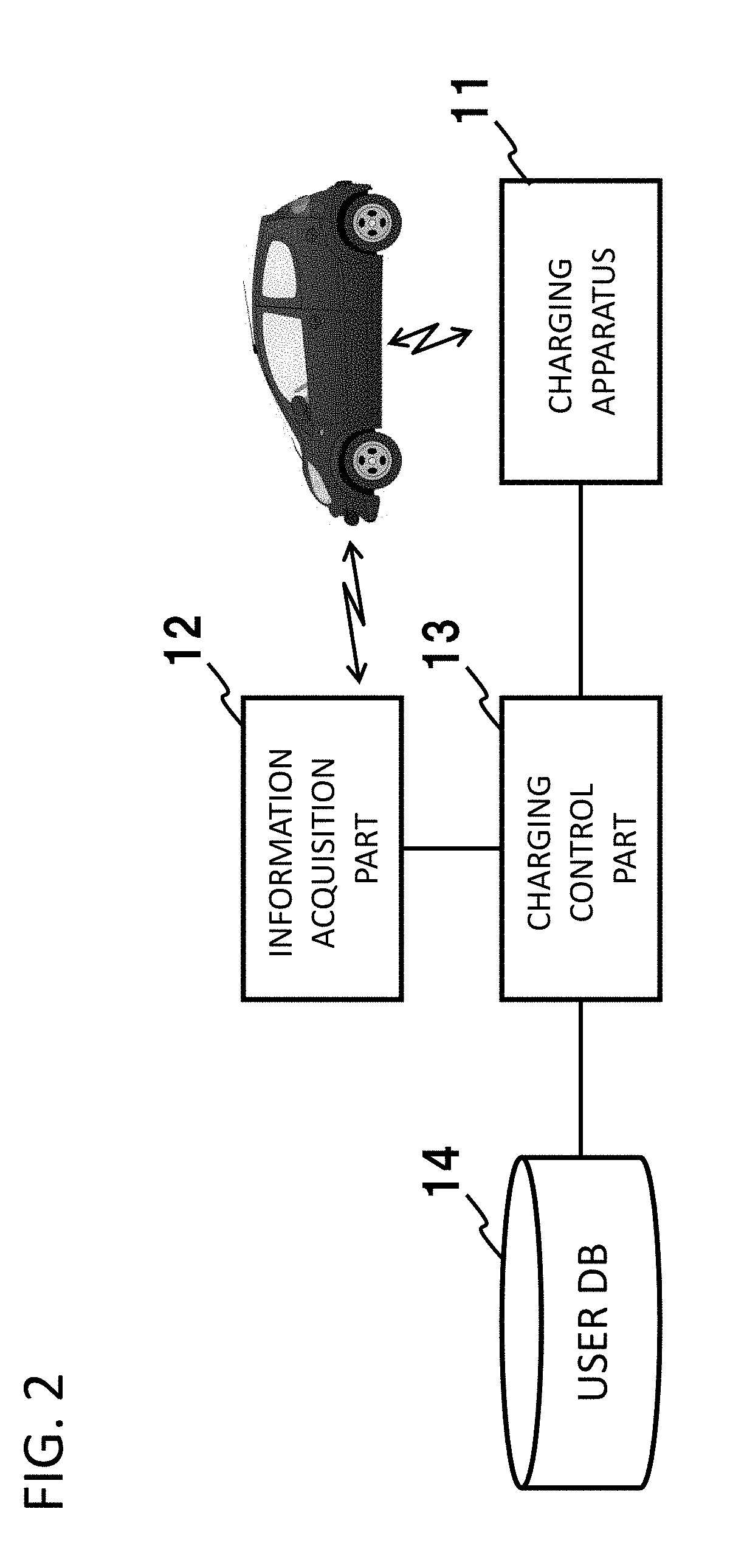
[0034]Next, a first exemplary embodiment of the present disclosure will be described in detail with reference to drawings. FIG. 2 illustrates a configuration of a vehicle charging system according to the first exemplary embodiment of the present disclosure. As illustrated in FIG. 2, the configuration includes a charging apparatus 11, an information acquisition part 12, a charging control part 13, and a user database (hereinafter, referred to as a user DB) 14.

[0035]The charging apparatus 11 is a non-contact charging apparatus that performs non-contact charging on a battery of a vehicle by facing a power receiving coil (a charging port) mounted on the vehicle. The non-contact charging method is not particularly limited. For example, an electromagnetic induction method or a resonance method may be used. When the resonance method is used, power is transmitted from a power transmitting coil included in the charging apparatus 11 to the power receiving coil by coupled resonance (resonance)...

second exemplary embodiment

[0045]Next, a second exemplary embodiment obtained by changing the above first exemplary embodiment will be described in detail with reference to drawings. FIG. 5 illustrates a configuration of a vehicle charging system according to the second exemplary embodiment of the present disclosure. This configuration differs from that according to the first exemplary embodiment illustrated in FIG. 2 in that the configuration includes information acquisition part 12a that can acquire a plurality of kinds of information. Since other basic configurations and operations according to the second exemplary embodiment are the same as those according to the first exemplary embodiment, the following description will be made with a focus on the difference.

[0046]The information acquisition part 12a acquires two or more kinds of information as the information for determining whether to allow charging. While a plurality of information acquisition parts 12a are arranged in the example in FIG. 5, a single ...

third exemplary embodiment

[0052]Next, a third exemplary embodiment obtained by changing the above second exemplary embodiment will be described in detail with reference to a drawing. FIG. 8 illustrates an example of information held in a user DB 14 according to the third exemplary embodiment of the present disclosure. In the present exemplary embodiment, in addition to the information for determining whether to allow charging, a field “charging condition” which is used for determining whether to allow charging is added to the user DB 14.

[0053]Charging control part 13 according to the present exemplary embodiment also serves as second information acquisition part configured to acquire charging condition information and determines whether each item of information received from information acquisition part 12a is registered in the user DB 14 and whether a corresponding condition(s) set as the field “charging condition” is satisfied. For example, in the case of a user A in FIG. 8, a condition “the unit charging ...


PUM


Abstract

A vehicle charging system includes: a non-contact charging apparatus that performs non-contact charging on a battery of a vehicle by facing a power receiving coil mounted on the vehicle; an information acquisition part configured to acquire, from the vehicle, information for determining whether to allow charging on the vehicle; and a charging control part configured to control a charging operation of the charging apparatus based on information acquired by the information acquisition part.

Description

REFERENCE TO RELATED APPLICATION[0001]This application is a national stage application of International Application No. PCT / JP2017 / 010642 entitled Vehicle Charging System, and Vehicle Charging Method,” filed on Mar. 17, 2016, which claims priority to Japanese Patent Application No. 2016-053407 filed on Mar. 17, 2016, the disclosures of which are hereby incorporated by reference in their entirety.FIELD[0002]The present invention relates to a vehicle charging system, a parking lot system, and a vehicle charging method. In particular, it relates to a vehicle charging system, a parking lot system, and a vehicle charging method for performing non-contact charging on batteries mounted on vehicles.BACKGROUND[0003]In recent years, methods for performing non-contact charging on batteries mounted on vehicles have been discussed. For example, PTLs 1 to 3 disclose configurations in which charging is performed by disposing a non-contact charging apparatus on a road surface or a parking lot and m...

Claims


Application Information

Patent Timeline
IPC IPC(8): B60L11/18E04H6/42G06Q50/06G06Q50/10H02J50/10H02J50/80H02J7/00
CPCB60L11/18E04H6/42G06Q50/06G06Q50/10H02J50/10H02J50/80H02J7/00B60M7/00E04H6/424B60L53/12B60L53/65G06Q10/0631H02J2310/48Y02T90/167Y02T10/70Y02T10/7072Y02T90/14Y02T90/12Y04S30/14Y04S20/222Y02B70/3225H02J7/0013H02J7/0042G06Q50/40
Inventor KONDO, YASUAKIFUKUBAYASHI, YUICHIRO
Owner NEC CORP
Why Eureka
Try Eureka