Cabin outflow air energy optimized cabin pressurizing system

a cabin and pressurizing system technology, applied in the direction of energy-efficient board measures, air-treatment apparatus arrangements, transportation and packaging, etc., can solve the problems of large power consumption of cabin pressurizing functions at altitude, waste of energy, and only partially used energy for generating bleed air

Active Publication Date: 2019-02-07
HONEYWELL INT INC
View PDF4 Cites 2 Cited by
  • Summary
  • Abstract
  • Description
  • Claims
  • Application Information

AI Technical Summary

Problems solved by technology

However, the cabin pressurization function consumes the largest amount of power at altitude even when the bleed condition (pressure) matches the environmental control system (ECS) demand.
The energy used to generate bleed air is only partially used, and a good portion of the energy is wasted due to the mismatch between the main engine (ME) operating conditions and cabin pressurization and air conditioning needs through various flight segments.
Recent movement towards More Electric Aircraft (MEA) uses cabin air compressors to pressurize ambient air to match the cabin pressure and air conditioning so little energy is wasted, but the cabin air compressor (CAC) is less efficient than the main engine compressor, and the operation is not at peak efficiency.
Failure mode conditions and redundancy requirements make the system even more complex and heavy.

Method used


Image

  • Cabin outflow air energy optimized cabin pressurizing system
  • Cabin outflow air energy optimized cabin pressurizing system
  • Cabin outflow air energy optimized cabin pressurizing system

Examples


Embodiment Construction

[0013]The following detailed description is of the best currently contemplated modes of carrying out the invention. The description is not to be taken in a limiting sense, but is made merely for the purpose of illustrating the general principles of the invention, since the scope of the invention is best defined by the appended claims.

[0014]Various inventive features are described below that can each be used independently of one another or in combination with other features. However, any single inventive feature may not address any of the problems discussed above or may only address one of the problems discussed above. Further, one or more of the problems discussed above may not be fully addressed by any of the features described below.

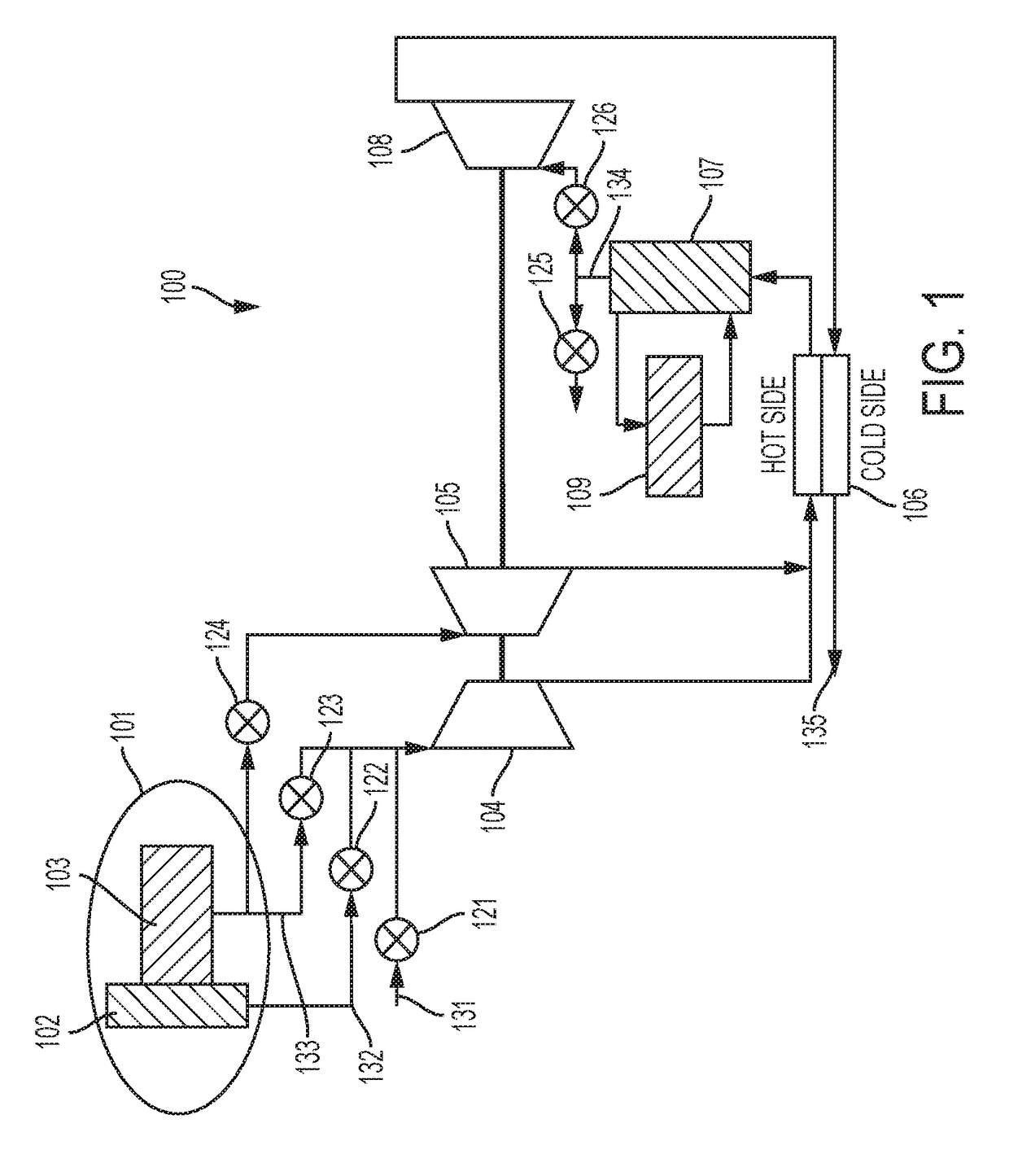
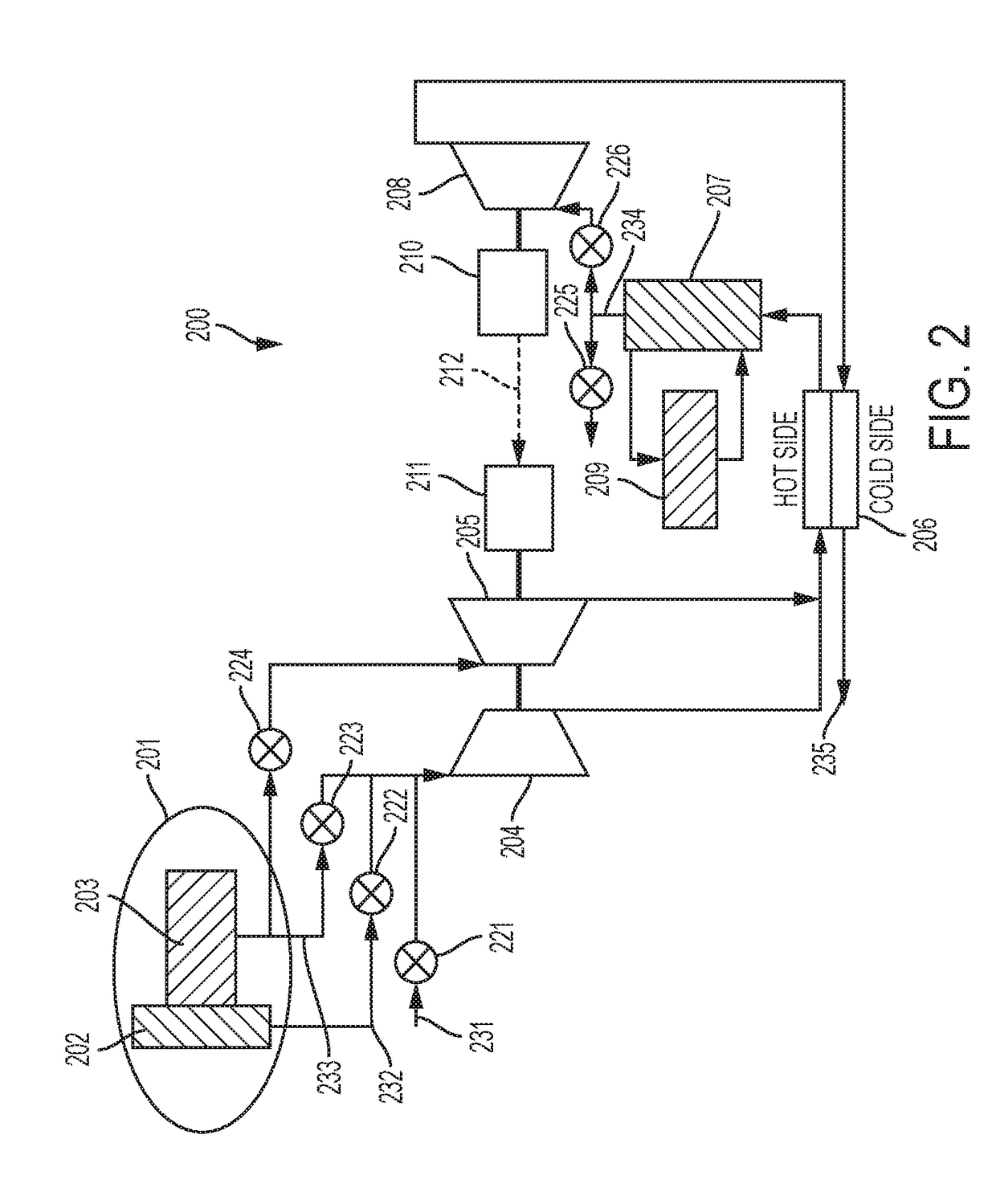
[0015]Broadly, the present invention provides a pressurization system that can use, in the context of an aircraft for example, engine fan air boosted by a boost compressor, which is powered by a cabin outflow air turbine (COT), and then cooled by the C...


PUM


Abstract

A pressurization system includes a first compressor that receives a ram air, a fan air, or engine air; a first turbine that is on a common shaft with the first compressor and wherein the first turbine receives an engine air; a main heat exchanger downstream of the first compressor and the first turbine; an internal environment suitable for human occupants and downstream of the main heat exchanger; a second turbine downstream of the internal environment; the second turbine may be on the common shaft with the first compressor and first turbine; or a generator downstream of the second turbine; a motor downstream of the generator; and wherein the motor drives the first compressor.

Description

BACKGROUND OF THE INVENTION[0001]The present invention generally relates to environmental control systems and, more particularly, to apparatus and methods for pressurizing an occupant environment of a vehicle.[0002]In aircraft, traditional pneumatic systems use main engine bleed air to pressurize and condition the cabin. This approach can be compact and elegant.[0003]However, the cabin pressurization function consumes the largest amount of power at altitude even when the bleed condition (pressure) matches the environmental control system (ECS) demand. The energy used to generate bleed air is only partially used, and a good portion of the energy is wasted due to the mismatch between the main engine (ME) operating conditions and cabin pressurization and air conditioning needs through various flight segments.[0004]Recent movement towards More Electric Aircraft (MEA) uses cabin air compressors to pressurize ambient air to match the cabin pressure and air conditioning so little energy is...

Claims


Application Information

Patent Timeline
Patent Type & Authority Applications(United States)
IPC IPC(8): B64D13/02B64D13/06
CPCB64D13/02B64D13/06B64D2013/0618B64D2013/0611B64D2013/0688B64D2013/0644B64D2013/0648Y02T50/50
Inventor LO, CHARLES
Owner HONEYWELL INT INC
Why Eureka
Try Eureka