
Information transfer mechanism for processing apparatus

Active Publication Date: 2019-02-07
DISCO CORP
View PDF7 Cites 0 Cited by
  • Summary
  • Abstract
  • Description
  • Claims
  • Application Information

AI Technical Summary

Benefits of technology

The present invention provides an information transfer mechanism for a factory with multiple processing apparatus. The mechanism helps to identify which processing apparatus is generating notice information. This helps the operator to quickly respond to the notice information and take appropriate action.

Problems solved by technology

Providing a plurality of processing apparatus that generate a common warning sound are installed in a factory, when the warning sound is being generated by one of the processing apparatus, an operator finds it difficult to quickly confirm which processing apparatus is generating the warning sound.
Furthermore, when a warning sound regarding an emergency situation and a notice sound regarding a situation as much as an announcement are being simultaneously generated by different processing apparatus, individually, an operator also finds it difficult to instinctively determine which processing apparatus is generating the warning sound and which processing apparatus is generating the notice sound even if securing a certain distance to see the group processing apparatus.
Consequently, the operator may delay dealing with the emergency situation.

Method used


Image

  • Information transfer mechanism for processing apparatus
  • Information transfer mechanism for processing apparatus
  • Information transfer mechanism for processing apparatus

Examples


embodiment 1

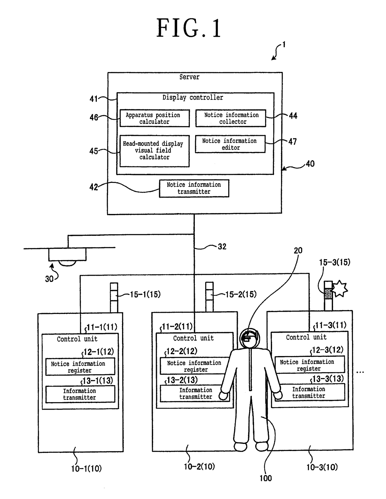
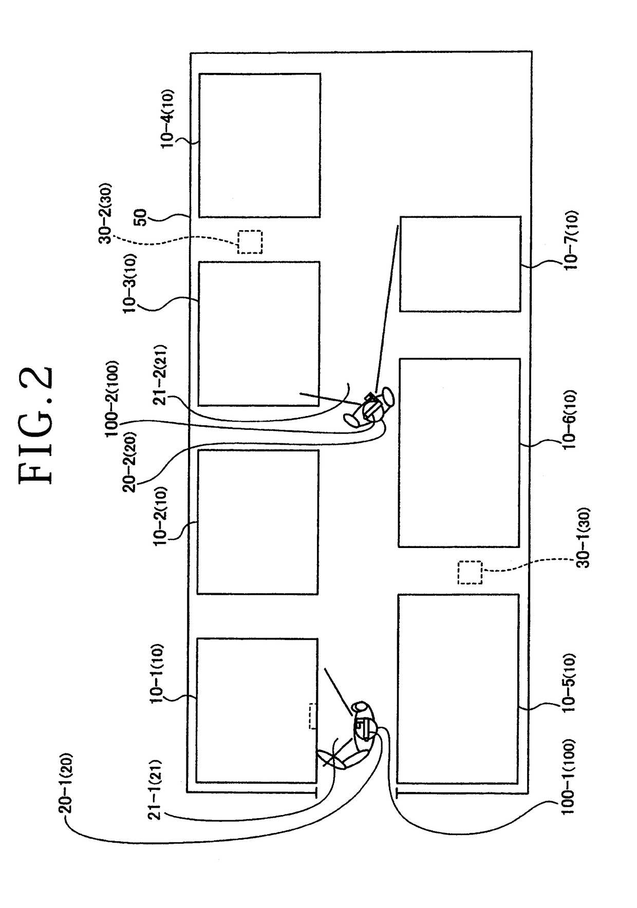
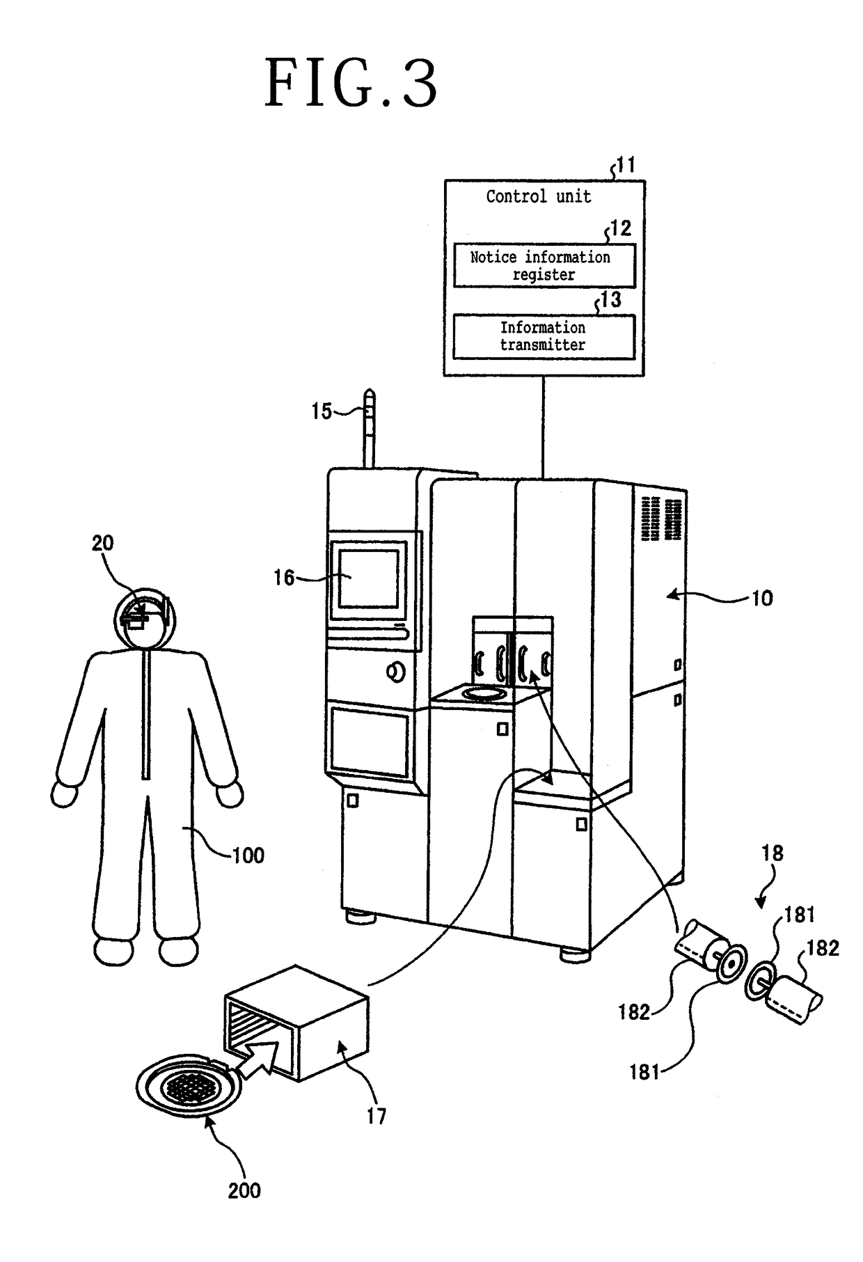
[0020]An information transfer mechanism 1 for processing apparatus according to Embodiment 1 of the present invention will be described below with reference to the drawings. FIG. 1 is a diagram depicting a configurational example of the information transfer mechanism 1 for processing apparatus according to Embodiment 1, and FIG. 2 is a plan view depicting a configurational example of the inside of a compartment in a factory where the information transfer mechanism 1 for processing apparatus depicted in FIG. 1 is employed. The information transfer mechanism 1 for processing apparatus is a mechanism or system for transferring information of processing apparatus 10-1, 10-2, 10-3, . . . to an operator 100. As depicted in FIG. 1, the information transfer mechanism 1 for processing apparatus has a plurality of processing apparatus 10-1, 10-2, 10-3, a head-mounted display 20, a head-mounted display detecting mechanism 30, and a server 40. In case the processing apparatus 10-1, 10-2, 10-3, ...

embodiment 2

[0073]An information transfer mechanism 2 for processing apparatus according to Embodiment 2 of the present invention will be described below with reference to the drawings. FIG. 8 is a diagram depicting a configurational example of the information transfer mechanism 2 for processing apparatus according to Embodiment 2 and FIG. 9 is a front elevational view depicting a head-mounted display included in the information transfer mechanism 2 for processing apparatus depicted in FIG. 8. Those parts depicted in FIGS. 8 and 9 which are identical to those according to Embodiment 1 are denoted by identical reference characters, and not be described in detail below.

[0074]The information transfer mechanism 2 for processing apparatus is a mechanism for transferring information of processing apparatus 10 to an operator 100. As depicted in FIG. 8, the information transfer mechanism 2 for processing apparatus has a plurality of processing apparatus 10, a head-mounted display 70, and a server 80. T...


PUM


Abstract

An information transfer mechanism includes processing apparatus and a head-mounted display, and transfers information of the processing apparatus to an operator. The processing apparatus has an information transmitter for transmitting positional information of the processing apparatus, individual identification information of the processing apparatus, and notice information to be notified to the operator. The head-mounted display receives the notice information of the processing apparatus which have entered a visual field thereof and displays the received notice information in overlapping relation to the scene of peripheral processing apparatus.

Description

BACKGROUND OF THE INVENTIONField of the Invention[0001]The present invention relates to an information transfer mechanism for processing apparatus.Description of the Related Art[0002]There is known a head-mounted display, used in factories, for displaying a guidance image for guiding the operator to a storage position where an object to be picked is stored, based on a captured image of a storage apparatus (see, for example, Japanese Patent Laid-Open No. 2015-160696). There is also known a head-mounted display, used in factories, for displaying manual information related to work depending on the position of a hand of the operator (see, for example, Japanese Patent Laid-Open No. 2010-164814).SUMMARY OF THE INVENTION[0003]There are known processing apparatus in which any of various plate-shaped workpieces such as semiconductor wafers and packaged substrates is held on a chuck table and processed from its exposed face side. These processing apparatus include a dicing apparatus, a grindi...

Claims


Application Information

Patent Timeline
IPC IPC(8): G02B27/01G05B19/042
CPCG02B27/0172G05B19/042G02B2027/0141G02B27/0179G02B2027/0187G05B2219/21063G05B2219/23148G02B27/017G06F3/013G08B7/06G08B21/18H01L21/30H01L21/67011G06F2203/012G02B2027/0138G02B2027/014
Inventor SEKIYA, KAZUMA
Owner DISCO CORP
Features
  • Generate Ideas
  • Intellectual Property
  • Life Sciences
  • Materials
  • Tech Scout
  • Unparalleled Data Quality
  • Higher Quality Content
  • 60% Fewer Hallucinations
Learn More