

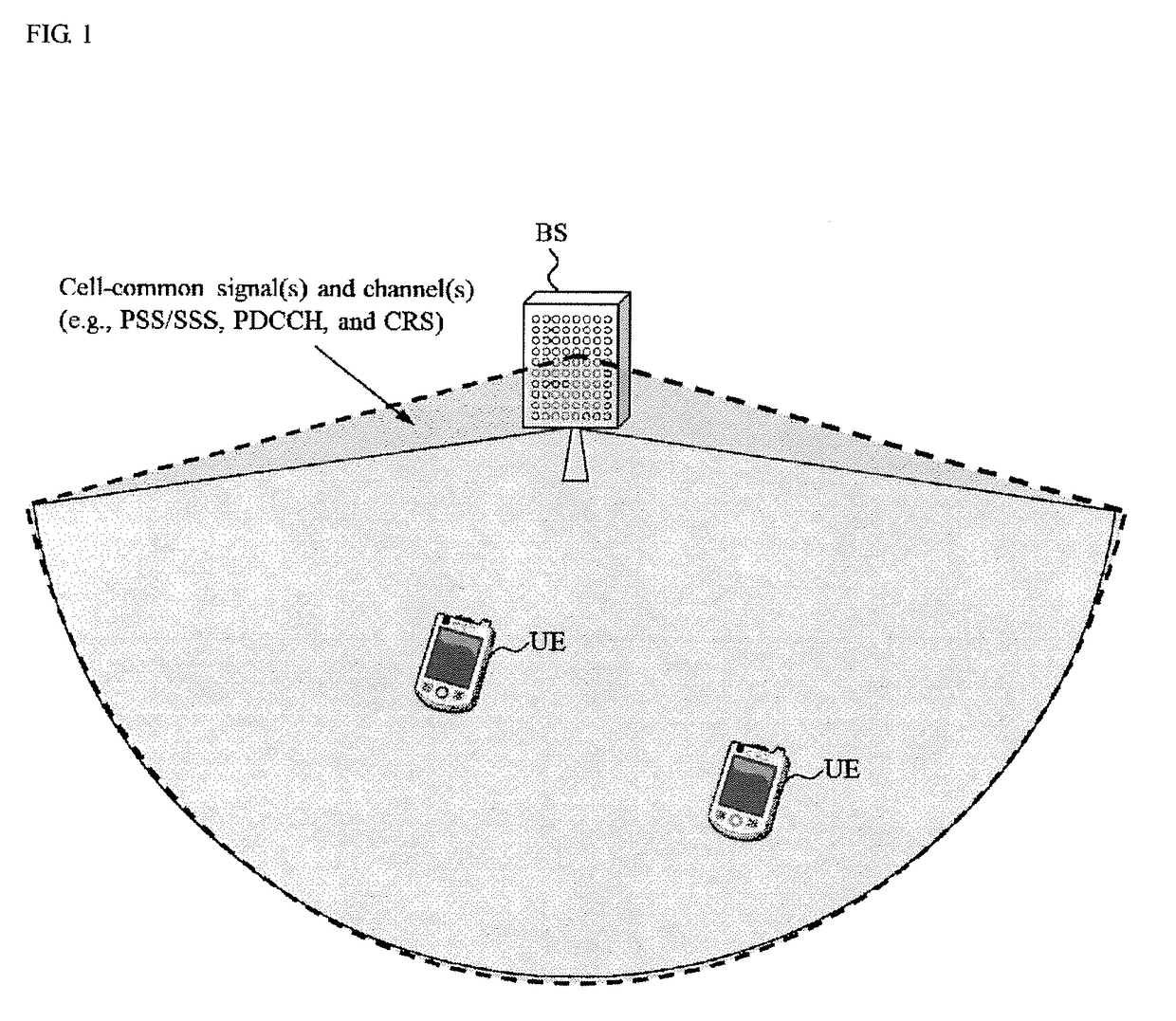
Beamforming common channels in 5g new radio
a common channel and beamforming technology, applied in the field of wireless communication, can solve the problems of beamforming cell-common signals that cannot be properly transmitted, and the coverage limitations of the higher frequency band
- Summary
- Abstract
- Description
- Claims
- Application Information
AI Technical Summary
Benefits of technology
Problems solved by technology
Method used
Image

Examples
first example
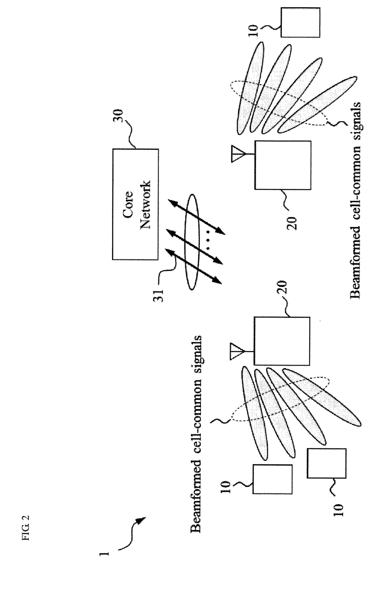
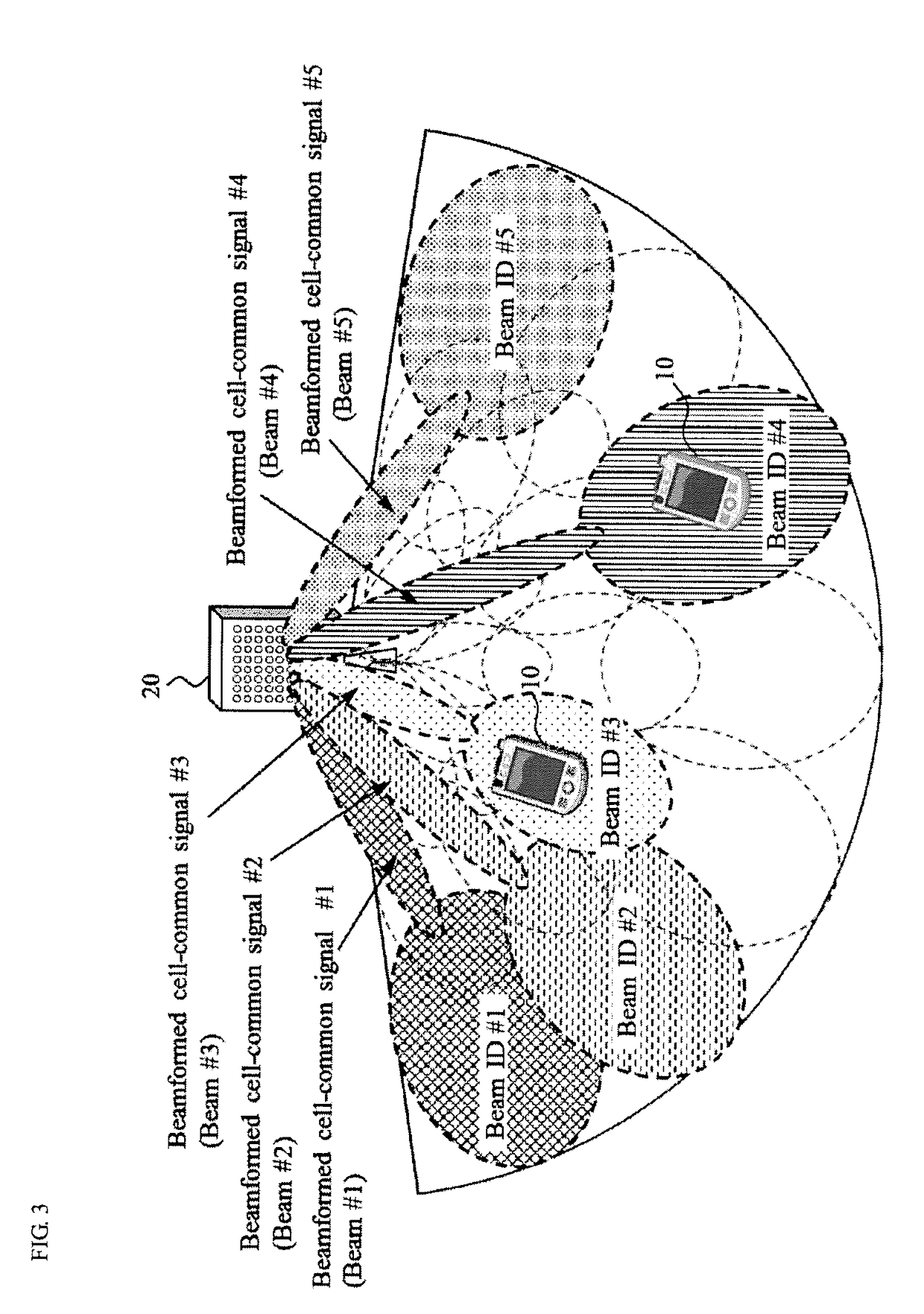
[0033]According to one or more embodiments of a first example of the present invention, the BS 20 may transmit multiple Synchronization Signals (SSs) (first signals) using respectively different beams (radio resources). The multiple SSs may comprise a common signal component (e.g., signal sequence). The UE 10 may receive all or part of the multiple SSs from the BS 20 and select a beam from the beams based on a reception quality of the multiple SSs. Then, the UE 10 may transmit feedback information including information indicating the selected beam to the BS 20.
[0034]FIG. 4 is a sequence diagram showing a beam determination (selection) scheme according to one or more embodiments of the first example of the present invention. As shown in FIG. 4, the BS 20 may transmit a plurality of BF SSs (first signal) using respectively different beams within the coverage of the BS 20 (step S101). The SSs may comprise a common signal component such as a signal sequence. Each of the beams may be ide...
second example
[0046]According to one or more embodiments of a second example of the present invention, the BS 20 may transmit a Non-precoded SS and the UE 10 may perform channel measurement based on the received SS and select the beam ID based on the channel measurement. Then, the BS 20 may determine a beam for the UE 10 based on the beam ID (or Precoding Matrix Indicator (PMI)) selected by the UE 10. The PMI can be determined based on legacy LTE codebooks or newly defined codebook.
[0047]FIG. 5 is a sequence diagram showing a beam determination (selection) scheme according to one or more embodiments of the second example of the present invention. As shown in FIG. 5, the BS 20 may transmit a Non-precoded SS within the coverage of the BS 20 (step S201). For example, like one or more embodiments of the first example, each of the BF SS includes the beam ID associated with the beam used for transmission of the BF SS. As another example, the SS may not be beamformed. As another example, the number of t...
third example
[0054]According to one or more embodiments of a third example of the present invention, the BS 20 may transmit BF predetermined signal(s) for the beam selection and the UE 10 may determine a beam based on the predetermined signal(s). For example, the predetermined signal for beam selection may be a CRS / CSI-RS / Discovery Reference Signal (DRS) based signal or a newly defined signal such as the MRS.
[0055]FIG. 6 is a sequence diagram showing a beam determination (selection) scheme according to one or more embodiments of the third example of the present invention. As shown in FIG. 6, the BS 20 may transmit the BF predetermined signal(s) for beam determination within the coverage of the BS 20 (step S301). For example, the predetermined signal can be used at least for timing synchronization. It can be also used to determine a beam ID associated with the beam used for transmission from the BS 20.
[0056]The UE 10 may receive the predetermined signal(s) from the BS 20. The UE 10 may obtain bea...
PUM
 Abstract
Description
Claims
Application Information