Multi-functional protective assemblies, systems including protective assemblies, and related methods

a protective assembly and multi-functional technology, applied in the field of multi-functional protective assemblies, systems including protective assemblies, can solve the problems of aerospace vehicles being damaged, aerospace vehicles being subject to aerodynamic heat, and aerospace vehicles being damaged

Active Publication Date: 2019-02-14
NORTHROP GRUMMAN SYST CORP
View PDF0 Cites 9 Cited by
  • Summary
  • Abstract
  • Description
  • Claims
  • Application Information

AI Technical Summary

Problems solved by technology

These environments may subject the aerospace vehicle to impact with foreign objects, such as rain, birds, rocks, dirt, micro-meteoroids, and other orbital debris, that may damage the vehicle.
Furthermore, the aerospace vehicle may also be subject to aerodynamic heat from atmospheric friction generated during launch and flight.
Additionally, the aerospace vehicle may also be subject to damage by electromagnetic phenomena, such as electromagnetic pulses and lightning strikes.
Consequently, adhesives are a relatively weak bonding method.
Accordingly, during operation of the vehicle, the protection system may at least partially break away from the aerospace vehicle and leave a portion of the vehicle exterior exposed to the harmful operating environments previously described.
Such adhesives also add weight to the aerospace vehicle, introduce additional mechanical impedance, thermal conductance, and shock propagation, have limited thermal properties, and are difficult to repair in the event of damage.
Using adhesive bonding to join layers of the protective system has similar disadvantages to adhesives provided at the interface between the protection system and the structural body of the aerospace vehicle.
For example, such adhesive bonding adds weight to the aerospace vehicle, forms a weak mechanical rather than chemical bond, and renders the distinct bond lines susceptible to failure by thermal and mechanical stresses.

Method used


Image

  • Multi-functional protective assemblies, systems including protective assemblies, and related methods
  • Multi-functional protective assemblies, systems including protective assemblies, and related methods
  • Multi-functional protective assemblies, systems including protective assemblies, and related methods

Examples


Embodiment Construction

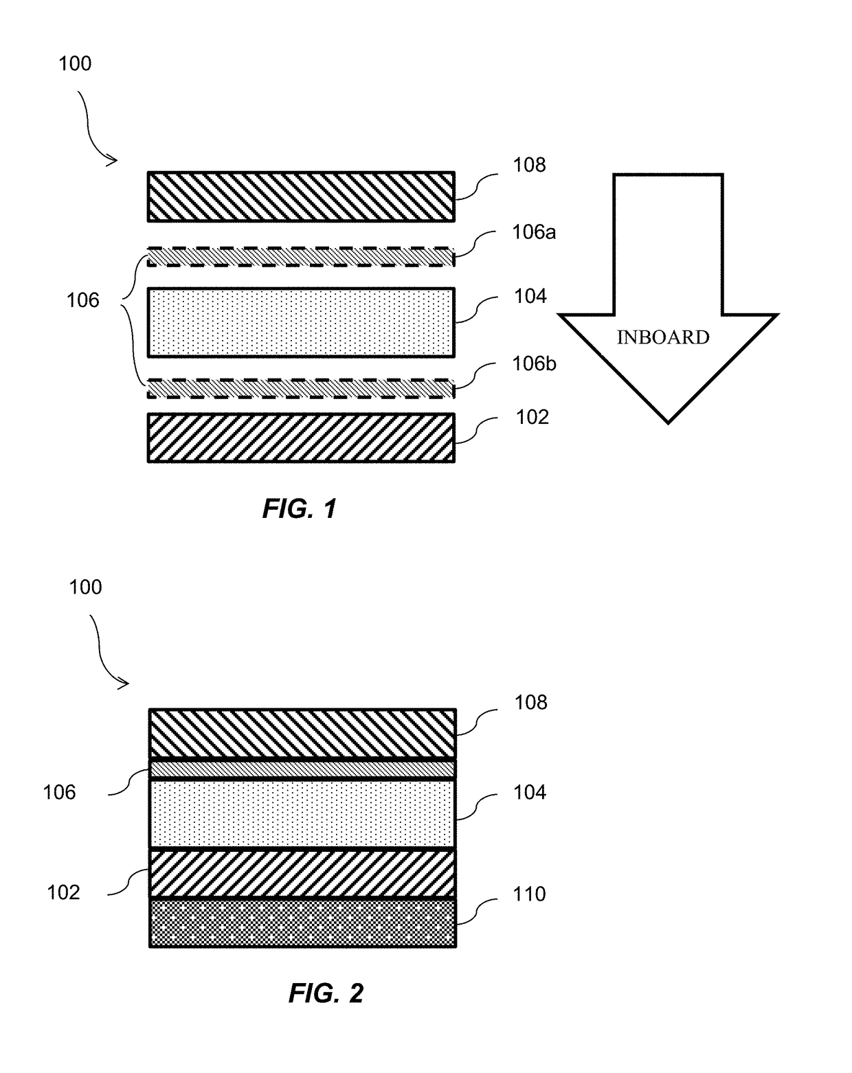
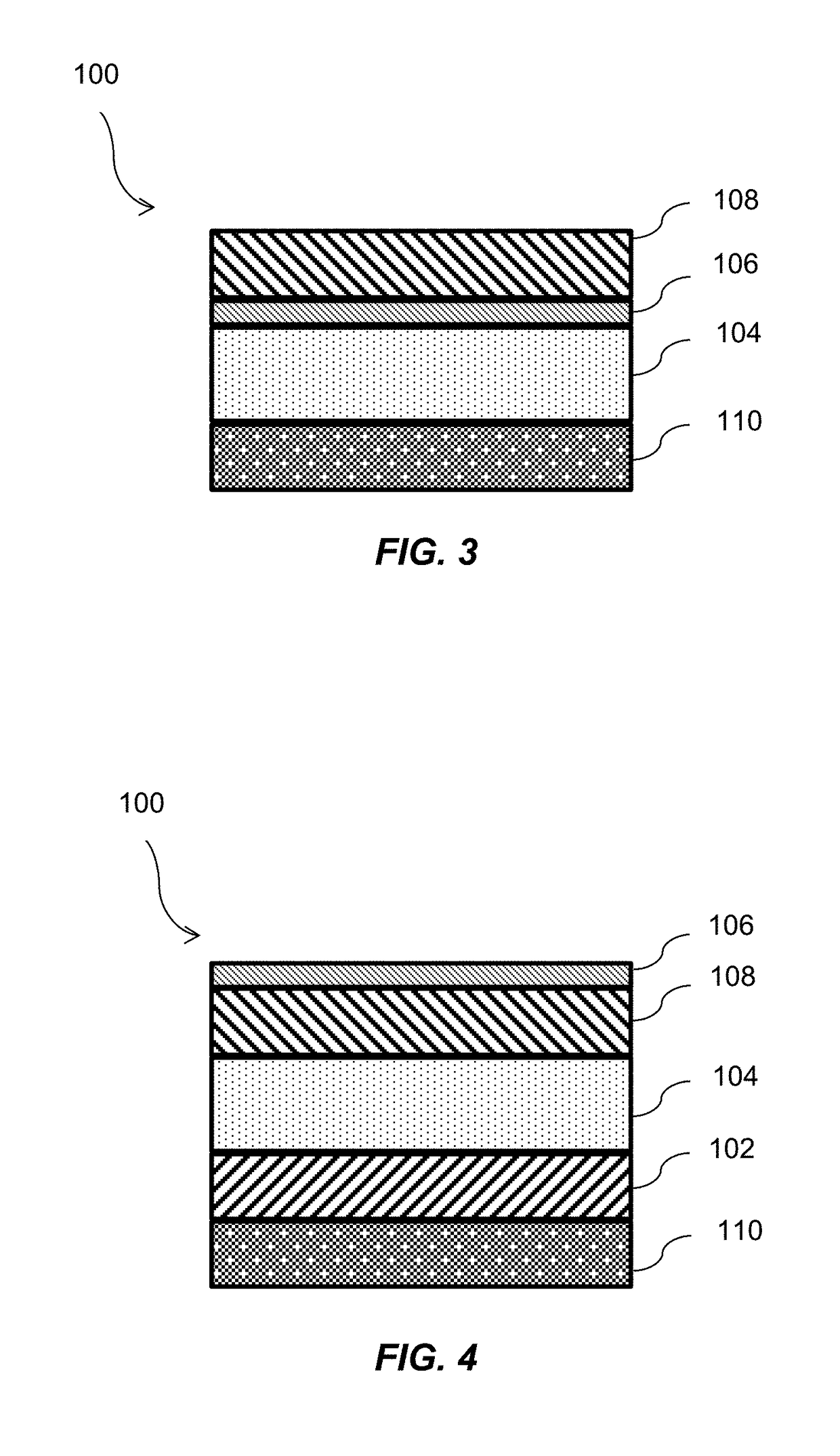
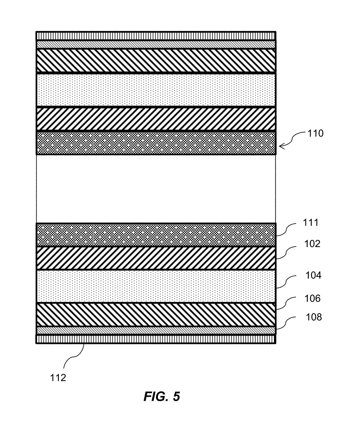
[0016]The illustrations presented herein are not actual views of any particular structure, device, assembly, protective structure (e.g., shield), or aerospace vehicle, but are merely idealized representations employed to describe example embodiments of the disclosure. The following description provides specific details of embodiments of the disclosure in order to provide a thorough description thereof. However, a person of ordinary skill in the art will understand that the embodiments of the disclosure may be practiced without employing many such specific details. Indeed, the embodiments of the disclosure may be practiced in conjunction with conventional techniques employed in the industry. In addition, the description provided below does not include all elements to form a complete structure or assembly. Only those process acts and structures necessary to understand the embodiments of the disclosure are described in detail below. Additional conventional acts and structures may be us...


PUM

PropertyMeasurementUnit
hypersonic velocitiesaaaaaaaaaa
particle diameteraaaaaaaaaa

Abstract

A protective assembly comprises a first region formulated and configured to provide protection from alpha, beta, and electromagnetic radiation and comprising a composite of particles and polymer; a second region formulated and configured to provide protection from ballistic impact and comprising a composite of fibers and polymer; and a third region formulated and configured to provide protection from thermal radiation and comprising a composite of particles, fiber, and polymer. The protective assembly may be provided on an aerospace structure. The protective assembly may be formed on the aerospace structure body using a co-curing process.

Description

CROSS-REFERENCE TO RELATED APPLICATION[0001]This application claims the benefit under 35 U.S.C. § 119(e) of U.S. Provisional Patent Application Ser. No. 62 / 545,340, filed Aug. 14, 2017, the disclosure of which is hereby incorporated herein in its entirety by this reference.TECHNICAL FIELD[0002]The disclosure, in various embodiments, relates generally to assemblies for shielding (e.g., protecting) an underlying structure, such as, for example, an aircraft or a spacecraft (e.g., aerospace structure), to systems including protective assemblies, and to methods of forming protective assemblies and systems.BACKGROUND[0003]Aerospace vehicles, such as aircraft and spacecraft, may have an external protection system to endure launch, in-flight, and space environments. These environments may subject the aerospace vehicle to impact with foreign objects, such as rain, birds, rocks, dirt, micro-meteoroids, and other orbital debris, that may damage the vehicle. In addition, these foreign objects m...

Claims


Application Information

Patent Timeline
Patent Type & Authority Applications(United States)
IPC IPC(8): B29C65/00B64G1/22B64G1/54B64G1/56B64G1/58
CPCB29C66/73754B29C66/71B29C66/721B29C66/72321B29C66/727B29C66/7314B29C66/7315B29C66/7392B64G1/226B64G1/54B64G1/56B64G1/58B29L2031/3076B32B15/02B32B37/10B32B2037/0092B32B2274/00B32B2305/38B32B2309/12B32B2309/68B32B2305/022B32B2305/08B32B2305/74B32B2307/212B32B2307/306B32B2307/558B32B2323/16B32B2327/18B32B2398/20B32B2605/18B64D7/00F41H5/0435F41H5/0464F41H5/0471F41H5/0492G21F1/106
Inventor STONE, STEVEN F.ARMENTROUT, MATTDEEMER, CHRISTOPHERMADSEN, CARL
Owner NORTHROP GRUMMAN SYST CORP
Why Eureka
Try Eureka