Power converter

Active Publication Date: 2019-02-14
FUJI ELECTRIC CO LTD
View PDF3 Cites 2 Cited by
  • Summary
  • Abstract
  • Description
  • Claims
  • Application Information

AI Technical Summary

Benefits of technology

The present invention aims to provide a power converter that can simplify the assembly work and reduce the weight when connecting multiple component-housing chassis. The invention achieves this by designing a support frame that protrudes from the component-housing chassis, which maintains mechanical strength in the connected chassis and reduces the weight.

Problems solved by technology

This can be problematic because increasing wall thickness results in an increase in weight and an inability to satisfy weight reduction requirements.
In particular, when the chassis is divided in the lengthwise direction into a plurality of component-housing chassis which are then connected together to form a connected chassis, it is difficult to maintain mechanical strength between the connected component-housing chassis, which results in a need to install a large number of hanging lugs as holding fixtures.
Moreover, it is difficult to make it easy to connect together the component-housing chassis.

Method used


Image

  • Power converter
  • Power converter
  • Power converter

Examples


Embodiment Construction

[0024]Embodiments of a power converter according to the present invention will be described with reference to figures. Note that the figures are only schematic illustrations and may be different from the actual components. Moreover, the embodiments described below are only examples of a device or method for implementing the technical concepts of the present invention and do not limit the configurations of the invention to the configurations presented below. In other words, the technical concepts of the present invention allow for various modifications to be made within the technical scope defined by the claims.

[0025]First, one embodiment of a power converter according to the present invention will be described.

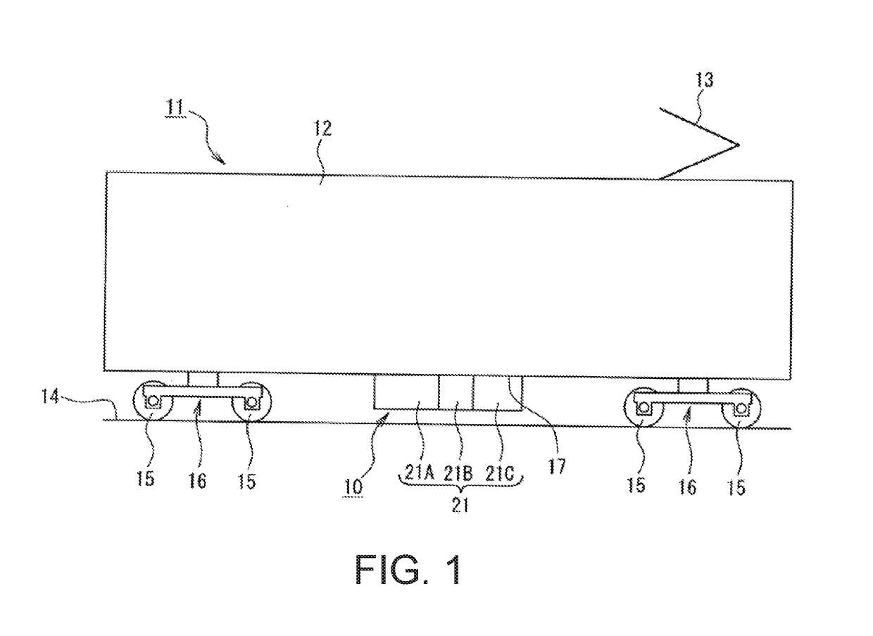
[0026]As illustrated in FIG. 1, in a railway vehicle 11 equipped with a power converter 10 according to the present invention, a pantograph 13 is installed on top of a vehicle body 12. Carts 16 which support wheels 15 respectively rotatably-contacting rails 14 on both lateral ...


PUM


Abstract

A power converter to be mounted to a mounting portion of a host in a suspended manner includes a plurality of component-housing chassis configured to be connected together parallel to the mounting portion, the plurality of component-housing chassis each containing parts for a power converter so that the plurality of component-housing chassis collectively constitute the power converter for the host, wherein at least one of the plurality of component-housing chassis has a support frame, the support frame protruding out so as to extend into at least an adjacent one of the component-housing chassis, wherein the at least adjacent one of the component-housing chassis has an insertion hole for inserting the support frame, and wherein the support frame is configured to be inserted into the insertion hole in the adjacent component-housing chassis and fixed to the adjacent component-housing chassis.

Description

BACKGROUND OF THE INVENTIONTechnical Field[0001]The present invention relates to a power converter to be installed in a railway vehicle, for example.Background Art[0002]One example of a previously proposed power converter to be mounted on the underfloor of a railway vehicle is the railway vehicle underfloor device disclosed in Patent Document 1.[0003]This railway vehicle underfloor device includes a power converter having a chassis assembled by riveting together a bottom wall unit, sidewall units, a top wall unit, and partition wall units. Here, electrical components and wiring are fixed to a bottom wall, sidewalls, partition walls, and a top wall in advance to create respective sub-units, and then these sub-units are riveted to the bottom wall unit, which includes the bottom wall and serves as a platform. Using two of the partition wall units, the interior of the chassis is divided into three compartments in the lengthwise direction. Filter capacitors are respectively arranged near...

Claims


Application Information

Patent Timeline
IPC IPC(8): B60L11/18B60L5/18B60M1/12H05K5/00H05K7/18H05K5/02
CPCB60L11/1812B60L5/18B60M1/12H05K5/0021H05K7/18H05K5/0204B61C3/00B60L2200/26H05K5/0213B60L53/22B61C17/00Y02T10/7072Y02T10/70Y02T90/14H05K7/14325
Inventor TAKAHASHI, KIYOSHI
Owner FUJI ELECTRIC CO LTD
Why Eureka
Try Eureka