

Energy regenerating damper
- Summary
- Abstract
- Description
- Claims
- Application Information
AI Technical Summary
Benefits of technology
Problems solved by technology
Method used
Image

Examples
first embodiment
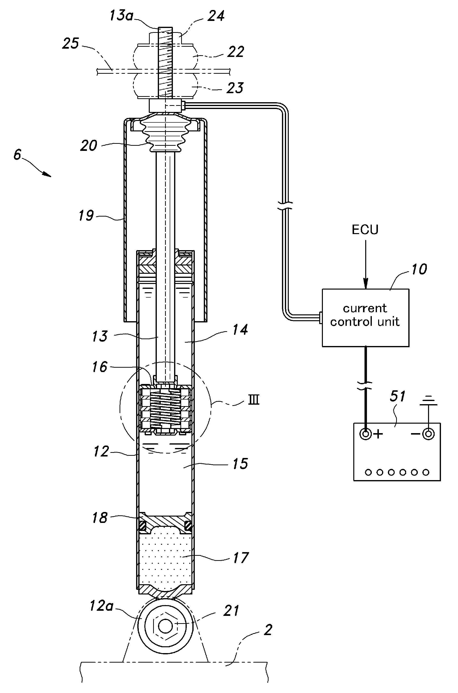
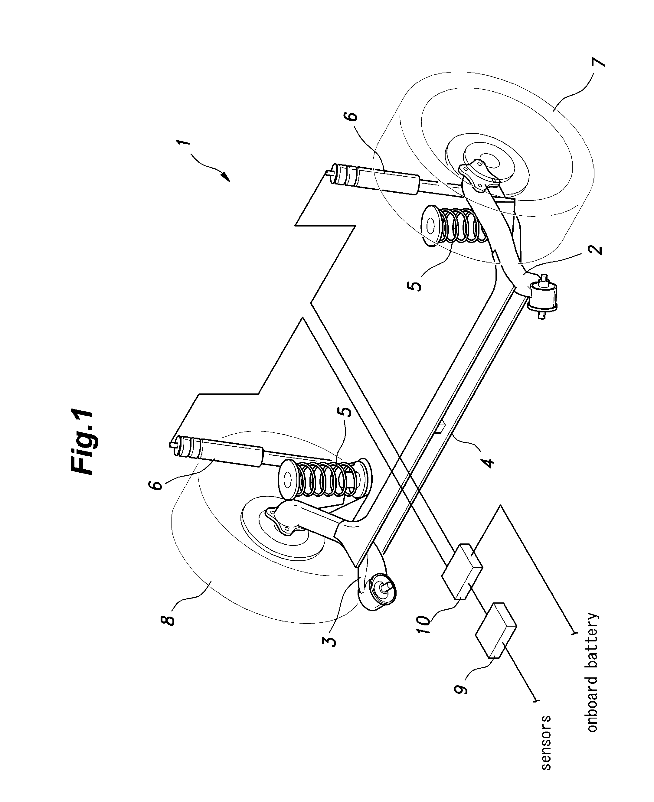
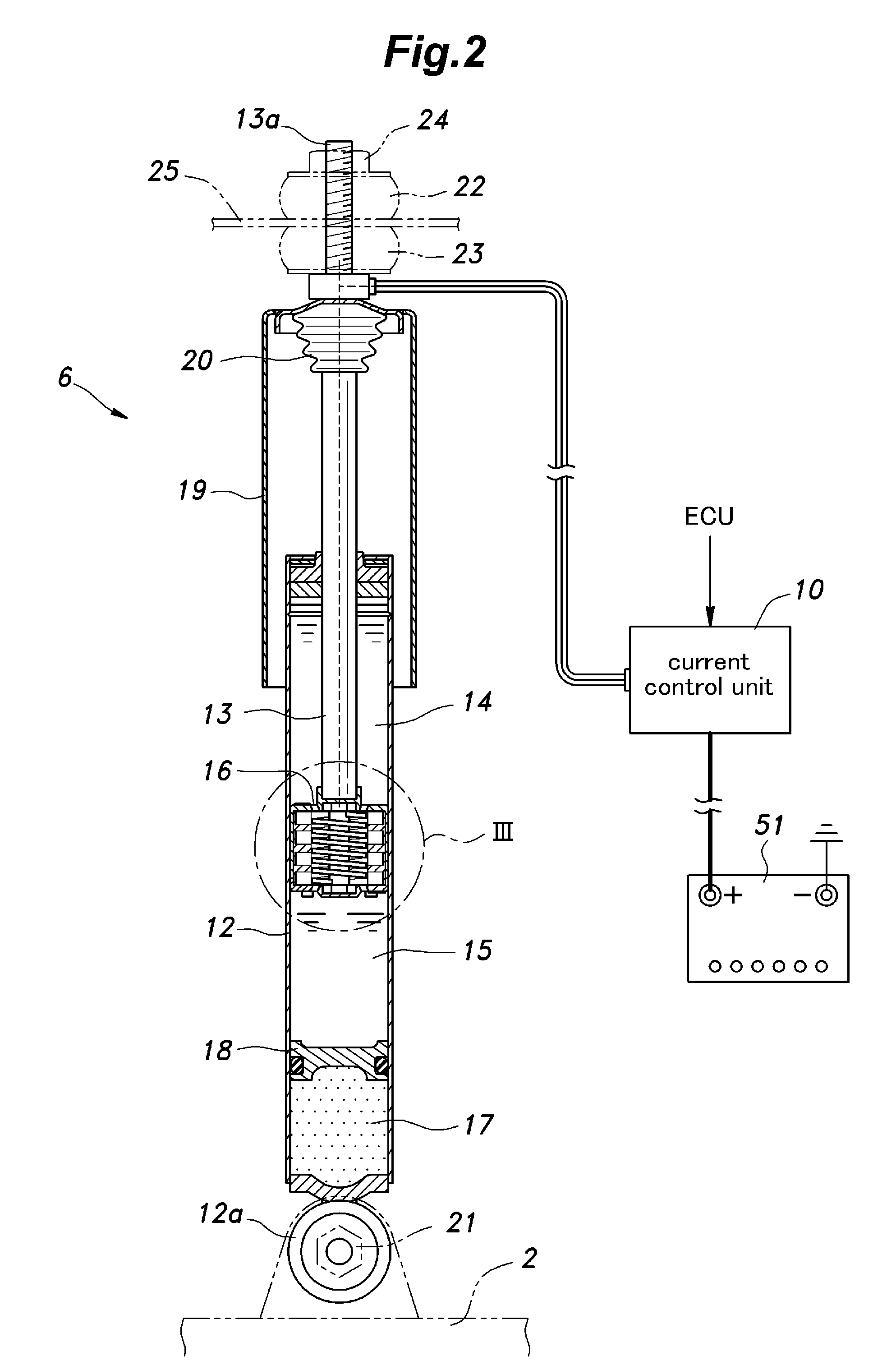
[0015]As shown in FIG. 1, a rear wheel suspension system 1 given as a first embodiment of the present invention essentially consists of a H-type torsion beam wheel suspension system, and comprises a pair of trailing arms 2 and 3 that support a pair of rear wheels 7 and 8, a torsion beam 4 connecting intermediate parts of the trailing arms 2 and 3 with each other, a pair of suspension springs consisting of coil springs 5 and a pair of dampers 6. Each damper 6 in this case consists of an energy regenerating damper, and a damper ECU 9 and a current control unit 10 installed in the trunk space variably control the power generating and damping actions of the damper 6.
[0016]As shown in FIG. 2, the damper 6 of the first embodiment is of a mono-tube type (de Carbon type), and comprises a cylinder 12 filled with working fluid, a damper rod 13 axially slidably received in the cylinder 12, a piston 16 attached to a free end of the damper rod 13 and separates the interior of the cylinder 12 int...
second embodiment
[0027]The second embodiment is similar to the first embodiment as far as the overall structure is concerned, and differs from the first embodiment in the structure of the piston. More specifically, as shown in FIG. 5, in the second embodiment, the stator 32 is fixed in an axially central part of the piston 16, and the rotor 33 is provided on the outside of the stator 32. As the mode of operation and the effect of the second embodiment are similar to those of the first embodiment, only the parts of the second embodiment that differ in structure from those of the first embodiment are described in the following.
[0028]As shown in FIG. 6 also, the stator 32 comprises a cylindrical stator main body 41 made of non-magnetic material such as aluminum and stator coils 42 incorporated in the outer periphery of the stator main body 41. The stator coils 42 are arranged along a concentric circle of the stator main body 41 as groups of four vertically aligned coils which are arranged at a regular ...
third embodiment
[0030]The third embodiment is also similar to the first embodiment as far as the overall structure is concerned, and differs from the first embodiment in the structure of the piston. More specifically, as shown in FIG. 7, in the third embodiment, a piston 16 for power generation and a piston 61 for damping are provided separately, and the rotor 33 is provided with screw members 62 similar to an aircraft propeller.
[0031]The piston 61 for damping is attached to the part of the damper rod 13 located above the piston 16 for power generation. The piston 61 for damping is disk-shaped, and is provided with a plurality of orifices 43 passed axially through the piston 61 and a pair of damping valves 34 and 35 for selectively closing the upper and lower ends of each orifice 43, respectively.
[0032]As shown in FIG. 8 also, the stator 32 comprises a cylindrical stator main body 41 made of non-magnetic material such as aluminum and stator coils 42 incorporated in the inner periphery of the stator...
PUM
 Abstract
Description
Claims
Application Information